Illumination device and projector

a technology of a projector and a device, which is applied in the direction of projectors, color television details, instruments, etc., can solve the problems of difficult manufacturing and control of the operation of the deformable mirror, and achieve the effect of high light use efficiency and efficient production

Active Publication Date: 2019-06-27
SEIKO EPSON CORP
View PDF0 Cites 2 Cited by
  • Summary
  • Abstract
  • Description
  • Claims
  • Application Information

AI Technical Summary

Benefits of technology

[0007]With the illumination device according to the first aspect, an image of the light-emitting end face of the rod can be formed on the lens surface of the second lens array. The image of the light-emitting end face functions as a secondary light source. Accordingly, it is possible to easily enlarge an image of the secondary light source formed on the second lens array compared with when light from the first collimate optical system is made incident on the lens integrator without using the rod. Consequently, it is possible to reduce speckles.
[0009]Since the illumination device includes the first lens array, a plurality of secondary light source images are formed on the second lens array. Since the illumination device includes the diffusing section, a region where the plurality of secondary light source images are formed is enlarged. Accordingly, it is possible to further reduce speckles.
[0011]With this configuration, since a diffusion state of light transmitted through the diffusing section temporally changes, a speckle pattern temporally changes. Since a time-averaged speckle pattern is recognized by an observer, speckle noise is less conspicuous than when the diffusing section does not rotate. Interference unevenness due to use of a laser light is reduced.
[0013]With this configuration, the secondary light source images can be expanded to a maximum size fit on the inner side of the contour of the second small lens. Accordingly, it is possible to reduce speckles by enlarging the secondary light source images.
[0015]The projector according to the second aspect includes the illumination device according to the first aspect. Therefore, the projector can display a high-quality image with speckle noise reduced.
[0017]With this configuration, each of partial beams of light emitted from the first lens array can be efficiently made incident on the image formation region of the light modulating device. Accordingly, it is possible to realize high light use efficiency.

Problems solved by technology

In the projector disclosed in JP-T-2011-507042, manufacturing and control of the operation of the deformable mirror are not easy.

Method used


Image

  • Illumination device and projector
  • Illumination device and projector
  • Illumination device and projector

Examples


first embodiment

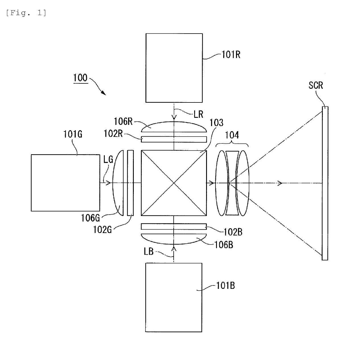
[0030]FIG. 1 is a schematic configuration diagram showing a projector in an embodiment.

[0031]As shown in FIG. 1, a projector 100 includes an illumination device for red light 101R, an illumination device for green light 101G, an illumination device for blue light 101B, a liquid-crystal light valve for red light 102R, a liquid-crystal light valve for green light 102G, a liquid-crystal light valve for blue light 102B, field lenses 106B, 106G, and 106R, a color synthesizing element 103, and a projection optical system 104.

[0032]In this embodiment, each of the illumination device for red light 101R, the illumination device for green light 101G, and the illumination device for blue light 101B corresponds to the “illumination device” in the claims. Each of the liquid-crystal light valve for red light 102R, the liquid-crystal light valve for green light 102G, and the liquid-crystal light valve for blue light 102B corresponds to the “light modulating device” in the claims.

[0033]The projecto...

second embodiment

[0074]Subsequently, an illumination device according to a second embodiment is explained. In this embodiment as well, only an illumination device for blue light is explained. Explanation is omitted concerning an illumination device for red light and an illumination device for green light. Note that components and members common to the first embodiment are denoted by the same reference numerals and signs. Explanation of the components and the members is omitted or simplified.

[0075]FIG. 6 is a diagram showing a schematic configuration of an illumination device for blue light 201B according to this embodiment.

[0076]As shown in FIG. 6, the illumination device for blue light 201B includes the light source device 10, the first collimate optical system 11, the condensing optical system 12, a rod 113, the second collimate optical system 14, the lens integrator 15, and the superimposing lens 16.

[0077]The rod 113 includes a light-incident end face 113a, a light-emitting end face 113b, and a d...

third embodiment

[0080]Subsequently, an illumination device according to a third embodiment is explained. In this embodiment as well, only an illumination device for blue light is explained. Explanation is omitted concerning an illumination device for red light and an illumination device for green light. Note that components and members common to the second embodiment are denoted by the same reference numerals and signs. Explanation of the components and the members is omitted or simplified.

[0081]FIG. 8 is a diagram showing a schematic configuration of an illumination device for blue light 301B according to this embodiment.

[0082]As shown in FIG. 8, the illumination device for blue light 301B includes the light source device 10, the first collimate optical system 11, the condensing optical system 12, a diffusion plate 18, the rod 113, the second collimate optical system 14, the lens integrator 15, and the superimposing lens 16.

[0083]That is, the illumination device for blue light 301B in this embodim...


PUM


Abstract

An illumination device includes a light source device, a first collimate optical system on which a light beam emitted from the light source device is made incident, a condensing optical system provided at a post-stage of the first collimate optical system, a rod provided at a post-stage of the condensing optical system, a second collimate optical system provided at a post-stage of the rod, a lens integrator provided at a post-stage of the second collimate optical system, and a superimposing lens provided at a post-stage of the lens integrator. The lens integrator includes a first lens array and a second lens array provided at a post-stage of the first lens array. A light-emitting end face of the rod and a lens surface of the second lens array are substantially conjugate with each other.

Description

BACKGROUND1. Technical Field[0001]The present invention relates to an illumination device and a projector.2. Related Art[0002]JP-T-2011-507042 discloses a technique for reducing speckle noise using a deformable mirror in a projector in which a laser light source is used.[0003]JP-A-2015-64444 discloses that an EP value is introduced as an indicator of the size of speckles and the speckles can be reduced by increasing the EP value.[0004]In the projector disclosed in JP-T-2011-507042, manufacturing and control of the operation of the deformable mirror are not easy. Therefore, there has been a demand for simple means that can increase the EP value disclosed in JP-A-2015-64444.[0005]One aspect of the present invention has been devised in order to solve the problems described above, and one of objects thereof is to provide an illumination device with speckles reduced. One of objects of one aspect of the present invention is to provide a projector including the illumination device.SUMMARY[...

Claims


Application Information

Patent Timeline
Patent Type & Authority Applications(United States)
IPC IPC(8): G03B21/20G02B27/48
CPCG03B21/208G02B27/48G03B21/006G03B33/12G02B27/0955G03B21/2013G03B21/2033H04N9/3161H04N9/3152G03B21/14
Inventor AKIYAMA, KOICHI
Owner SEIKO EPSON CORP
Why Eureka
Try Eureka