Method for producing base material for optical fiber having deformed first clad, base material for optical fiber and optical fiber

Inactive Publication Date: 2004-01-20
SHIN ETSU CHEM IND CO LTD
View PDF15 Cites 3 Cited by
  • Summary
  • Abstract
  • Description
  • Claims
  • Application Information

AI Technical Summary

Problems solved by technology

However, it was quite difficult to realize it for a problem in production thereof.
Namely, breakages or cracks often occur on the surface of the base material in a process of cooling the porous quartz glass base material that is formed by sooting on the second core having a deformed shape, resulting in reduction of yield of the base material, and lowering of productivity.
However, there is a problem in production that not only wiredrawing of base material, but also a coa

Method used


Image

  • Method for producing base material for optical fiber having deformed first clad, base material for optical fiber and optical fiber
  • Method for producing base material for optical fiber having deformed first clad, base material for optical fiber and optical fiber

Examples


example

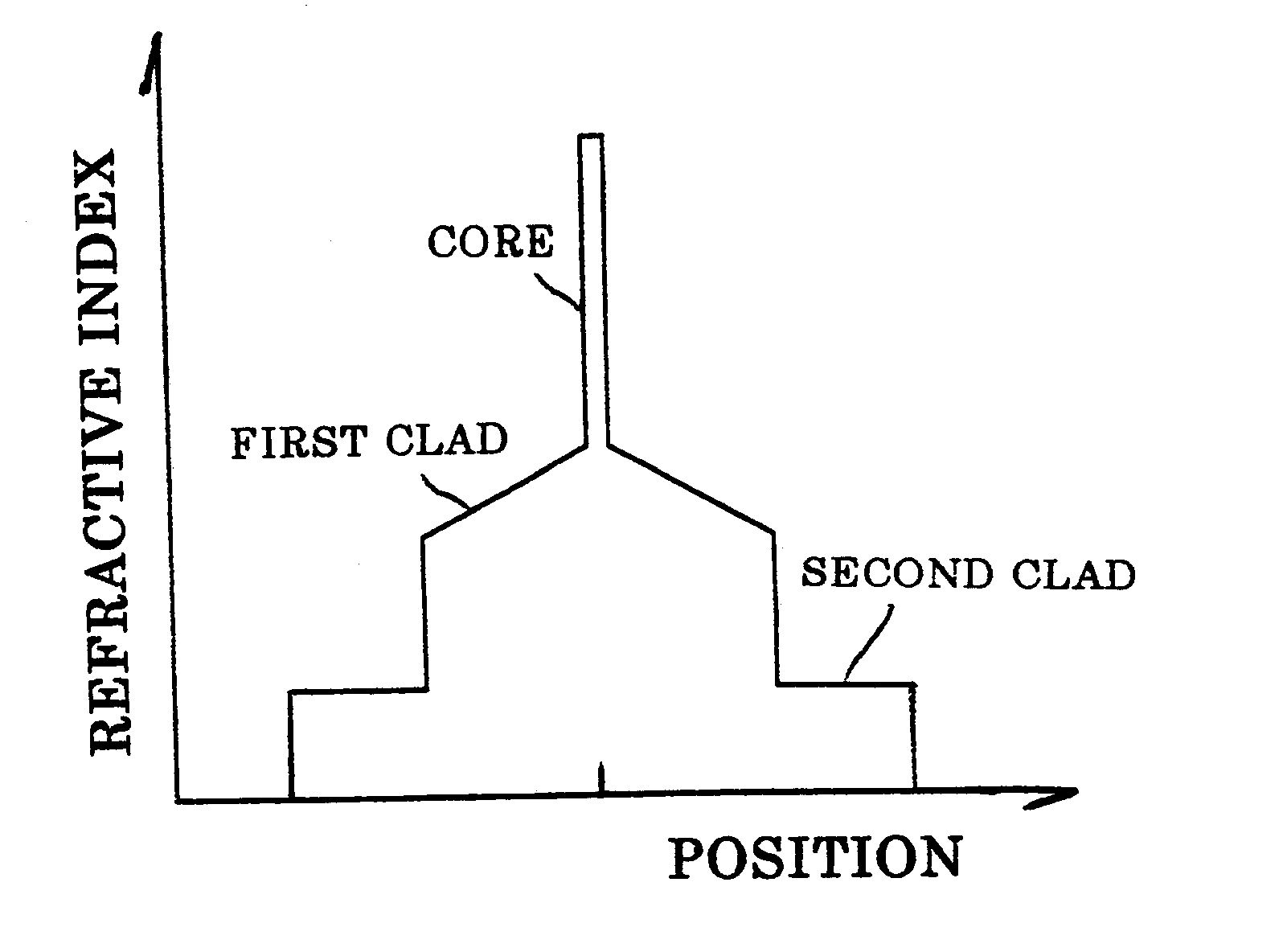
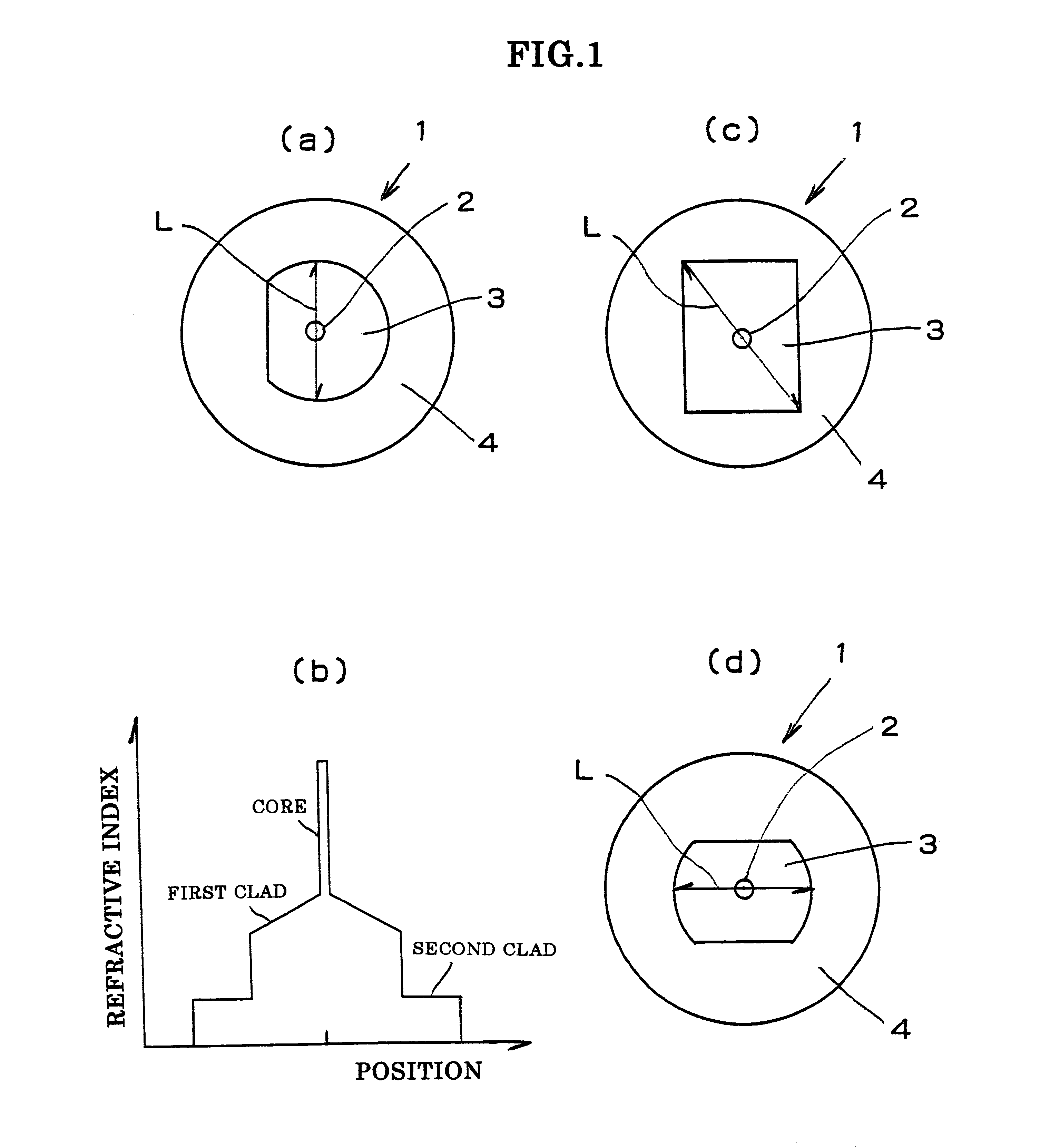
A glass rod was produced according to VAD method, which was then drawn to have a diameter of 3 mm, yielding a core rod. A difference in a refractive index of the core rod was +0.3% (based on pure quartz level).

A glass rod in the region of the first clad was produced according to VAD method, and drilling was conducted to form a hole having an inner diameter of 5 mm at the center of the glass rod. Then, the core rod produced above was inserted in the hole, and then was collapsed on a glass lathe to be unified. As described above, the glass rod having the core / the first clad was produced.

Then, it was drawn to have a diameter of 10 mm, and a part of the glass rod was ground to be linear so that the section may be D-shape. Porous glass fine particles were deposited around the glass rod having a section of D-shape according to VAD method, and was vitrified in an atmosphere of fluorine to yield a glass base material (preform) wherein the second clad was formed. Then the periphery of the pr...

example 2

A glass rod having a core and a first clad was drawn to have a diameter of 20 mm, and a part of the glass rod was ground to be linear so that the shape of the section may be D-shape. Porous glass fine particles were deposited around each of 20 glass rods having a section of D-shape according to VAD method. Cracks occurred in 20 glass rods all obtained by the conventional method. However, cracks did not occur in 16 of 20 glass rods obtained by the method of the present invention, and thereby the base material for the optical fiber having the second clad with a round section could be produced. In four of them, breakage and crack occurred in a step of cooling the porous glass fine particles after deposition.

The present invention is not limited to the above-described embodiment. The above-described embodiment is a mere example, and those having the substantially same structure as that described in the appended claims and providing the similar action and effects are included in the scope...


PUM

PropertyMeasurementUnit
Lengthaaaaaaaaaa

Abstract

There is disclosed a method for producing a base material for optical fiber having a deformed first clad consisting of at least a core, a first clad and a second clad, comprising a step of deforming a shape of a section of the first clad so that it may have at least one linear part when the first clad is formed around the core, a step of depositing porous glass fine particles as the second clad made of the same material as that of the first clad on a glass rod having the deformed first clad to form a porous glass base material, and a step of forming the second clad having a round section by vitrifying it. There can be provided a method for producing a base material for optical fiber wherein a lot of breakages or cracks on the surface of the base material can be prevented in a step of depositing porous glass fine particles for the second clad on the first clad, and base material for optical fiber having no defects, and an optical fiber having an efficient effect of being excited with excitation light.

Description

BACKGROUND OF INVENTION1. Field of the InventionThe present invention mainly relates to an optical fiber for amplification that corresponds to tendency of being high-powered of a light amplifier or a fiber laser, an base material for optical fiber that is a material therefor, and a method for producing it.2. Description of the Related ArtRecently, a light amplifier for system construction of DWDM (Dense Wavelength Division Multiplexing) has been strongly required to be high-power. Furthermore, there has been required high-power also in the field of fiber laser. In both cases, excitation light is introduced in quartz optical fiber wherein rare earth element is doped in the core, and emission of the rare earth element is used, and it is necessary for achievement of high-power to excite the core with the excitation light efficiently.Recently, there was proposed a method called clad pumping for the purpose as described above (Japanese Patent Application Laid-open (kokai) No. 11-72629).T...

Claims


Application Information

Patent Timeline
IPC IPC(8): C03B37/012G02B6/02C03B37/018G02B6/00
CPCC03B37/01225C03B37/01228C03B37/01231G02B6/03633C03B2203/12C03B2203/22G02B6/0283Y02P40/57G02B6/02
Inventor ABE, JUNMANTOKU, NOBUYASUMAKIKAWA, SHINJIEJIMA, SEIKI
Owner SHIN ETSU CHEM IND CO LTD
Why Eureka
Try Eureka