Image capturing device having improved bridge structure

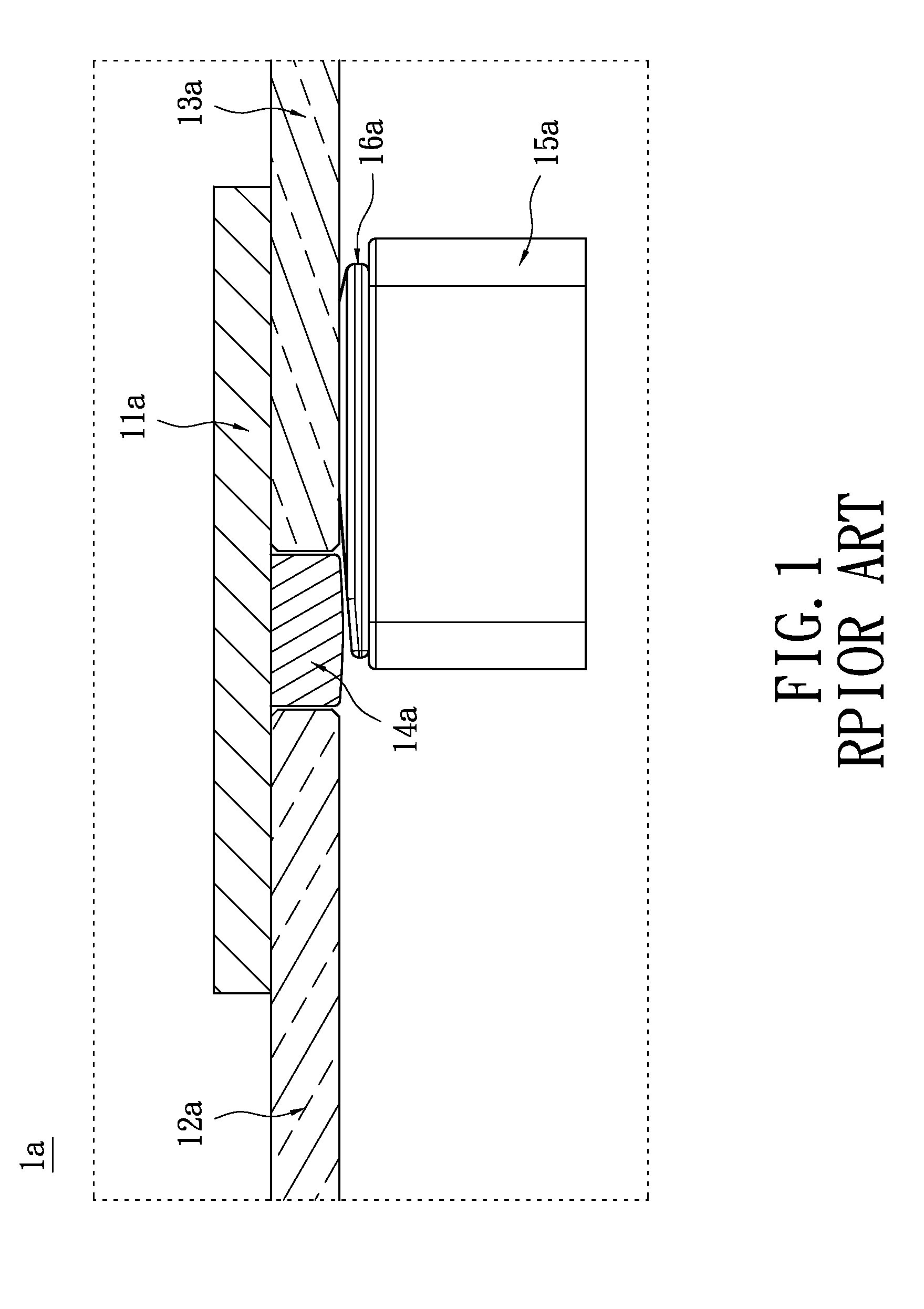
a bridge structure and image technology, applied in the field of image detection/capturing devices, can solve the problems of shortening the lifespan of the scanner la, difficult and impractical drilling a trough on the glasses without breaking, and not easy and suitable for manufacturing adf windows, so as to improve the bridge structure, increase the device's lifespan, and reduce the frictional resistance between

Inactive Publication Date: 2013-06-13
LITE ON ELECTRONICS (GUANGZHOU) LTD +1
View PDF1 Cites 0 Cited by
  • Summary
  • Abstract
  • Description
  • Claims
  • Application Information

AI Technical Summary

Benefits of technology

[0008]The object of the instant disclosure is to provide an image detecting / capturing device having an improved bridge structure. When the scanning module passes through the bridge structure, the slider will be moved on a roller to reduce the frictional resistance therebetween which will lead to abrasion, thus, increasing the lifespan of the device and maintaining the image quality in a better condition.
[0010]Based on the above, an image detecting / capturing device having an improved bridge structure is provided. The ADF transparent layer and the flatbed transparent layer have a roller mounted therebetween. The roller rotates swiftly to ensure a smooth operation of the scanning module between the ADF transparent layer and the flatbed transparent layer. Furthermore, the slider is moved by the rotation of the roller which has well replaced the typical sliding manner. Therefore, the frictional resistance therebetween can be decreased significantly to reduce damages to the slider from friction. Thus, the lifespan of the detecting device can be lengthened and the quality of the graphic can be maintained permanently in a better condition. On the other hand, in comparison to conventional bridge plates, the inclusion of the roller can simplify the structural design of the detecting device to reduce the manufacturing cost.

Problems solved by technology

Due to the fragile nature of glasses (which can be easily broken), drilling a trough on the glasses without breaking it is difficult and impractical.
Thus, it is not easy and suitable to manufacture the ADF window 12a and the flatbed window 13a as a single integrated glass structure.
After prolong usage, abrasive damage may be caused on the slider 16a and the bridge plate 14a due to friction, consequently shortening the lifespan of the scanner la, reducing the graphic quality, and producing unwelcomed noise during operation.

Method used


Image

  • Image capturing device having improved bridge structure
  • Image capturing device having improved bridge structure
  • Image capturing device having improved bridge structure

Examples


Embodiment Construction

[0020]Unless stated otherwise, all mentioned quantities are not intended to be limiting.

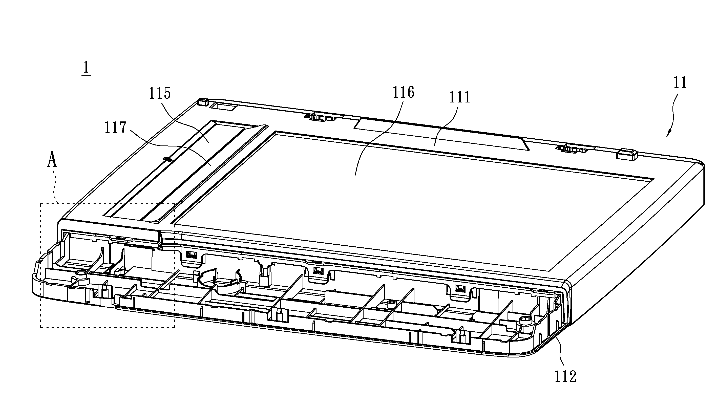
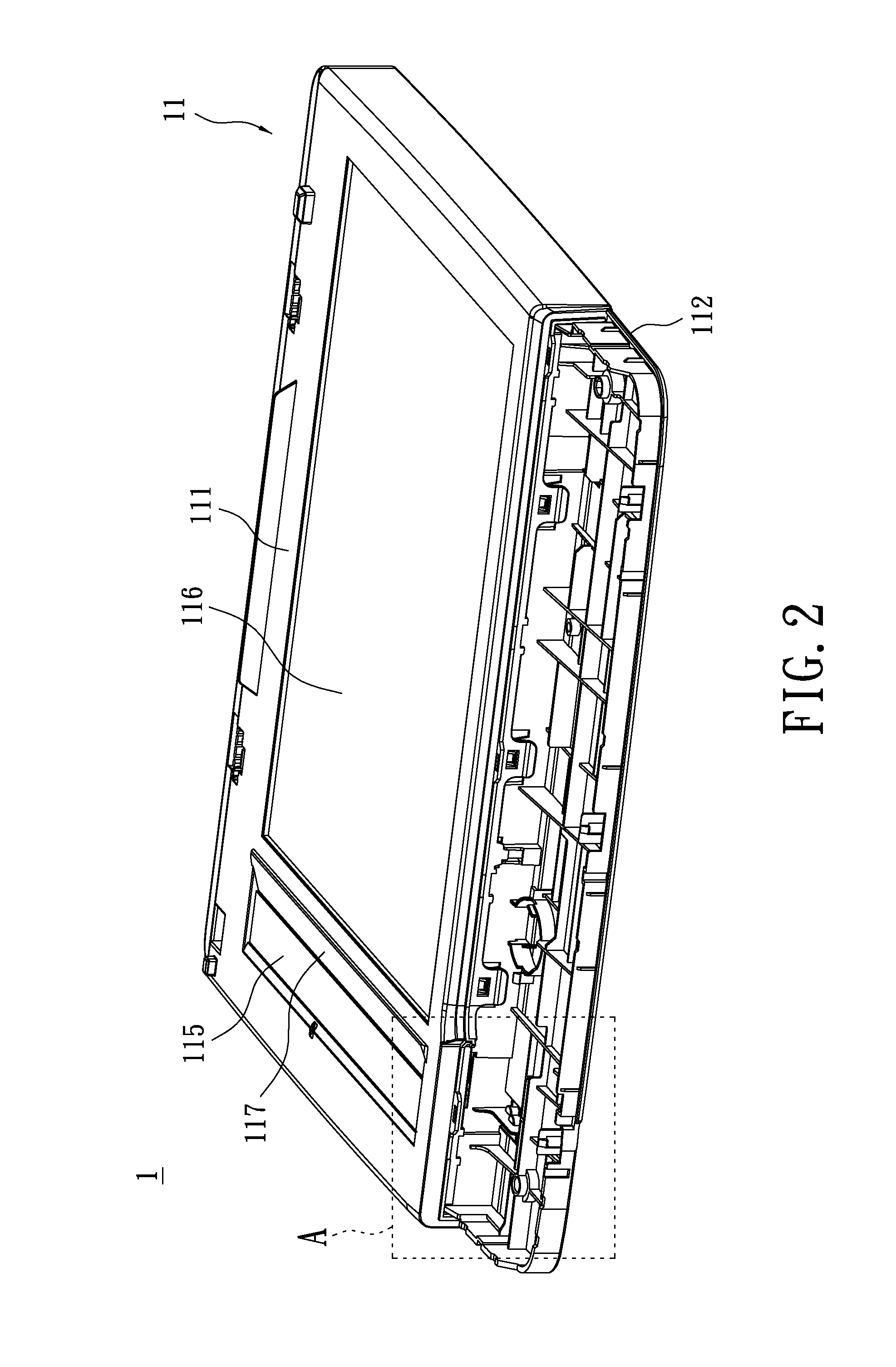
[0021]Please refer to FIGS. 2-4. An embodiment of the instant disclosure discloses an image detecting / capturing device 1 having an improved bridge structure. The detecting device 1 refers particularly to a scanner that utilizes contact image sensor (CIS) for image formation, which has a shallower depth of field. The CIS is a highly modularized component which may include an optical lens assembly and an electro-optical converting device. The CIS is commonly applied on scanners with thinner housings and quick switch-on functions.

[0022]The detecting device 1 includes a housing 11, a bridge structure 12, a scanning module 13 and a slider 14. The housing 11 has a cover 111 and a base 112, and is formed of the assembly of the cover 111 and the base 112. To provide further explanations, the cover 111 and the base 112 of the instant embodiment are two detachable components; however, the housing 11 can al...


PUM


Abstract

A detecting device having image capturing capability in a bridge structure is provided, which includes a housing, a bridge structure, a scanning module, and a slider. The housing has a plurality of inner walls. The bridge structure includes at least one roller, an ADF transparent layer, and a flatbed transparent layer. The roller is arranged on one of the inner walls between the ADF transparent layer, and the flatbed transparent layer. The scanning module is movably arranged below the ADF transparent layer, and the flatbed transparent layer. The scanning module and the roller are spaced apart from each other. The slider is arranged on the scanning module, where the slider has a glide plane arranged proximate to the ADF transparent layer, and the flatbed transparent layer. The roller rolls on the glide plane. Thus, the lifespan of the device may be extended through reduction of friction during scanning operation.

Description

BACKGROUND OF THE INVENTION[0001]1. Field of the Invention[0002]The instant disclosure relates to an image detecting / capturing device; in particular, to an image detecting / capturing device of contact image sensor (CIS) type having an improved bridge structure.[0003]2. Description of Related Art[0004]Conventional image scanners that utilize contact image sensors (CIS) for image formation (such as the scanner la shown in FIG. 1) include a housing 11a, an automatic document feeder (ADF) window 12a, a flatbed window 13a, a bridge plate 14a, a CIS scanning module 15a, and a slider 16a. The bridge plate 14a is arranged in the housing 11a between the ADF window 12a and the flatbed window 13a. [0005]Generally, in order to meet the demand for mass production under current technology constrains, the ADF window 12a and the flatbed window 13a have to be arranged as separate components. The scanning module 15a has to travel back and forth between the separately arranged ADF window 12a and the fl...

Claims


Application Information

Patent Timeline
Patent Type & Authority Applications(United States)
IPC IPC(8): H04N1/04
CPCH04N1/0464H04N1/1017H04N2201/02497H04N1/193H04N1/12
Inventor DING, RAYMOND
Owner LITE ON ELECTRONICS (GUANGZHOU) LTD
Why Eureka
Try Eureka