Electric power tool

a technology of electric power tools and power tools, which is applied in the direction of wrenches, portable power tools, screwdrivers, etc., can solve the problems of hindering the compactification of the electric power tools itself, increasing costs, etc., and achieves the effects of suppressing an increase in cost, easy to know the battery level drop, and simplified electric wiring

Active Publication Date: 2013-06-13
MAKITA CORP
View PDF2 Cites 0 Cited by
  • Summary
  • Abstract
  • Description
  • Claims
  • Application Information

AI Technical Summary

Benefits of technology

[0012]According to the first aspect, since one light emitter is used for a plurality of functions including an illumination function, even if the light emitter is used for the plurality of functions, electric wiring is simplified. This makes it possible to suppress an increase in cost and to achieve downsizing.
[0013]According to the second aspect, in addition to the effect of the first aspect, it is possible to easily know the decrease in the battery level by using the light emitter.
[0014]According to the third aspect, in addition to the effect of the first aspect, it is possible to easily recognize a function by t...

Problems solved by technology

In the conventional electric power tool, since the LED for an illumination function and the LED for a notification function to notify a battery level and the like are...

Method used


Image

  • Electric power tool
  • Electric power tool
  • Electric power tool

Examples


Embodiment Construction

[0024]An embodiment of the present invention is explained below with reference to drawings.

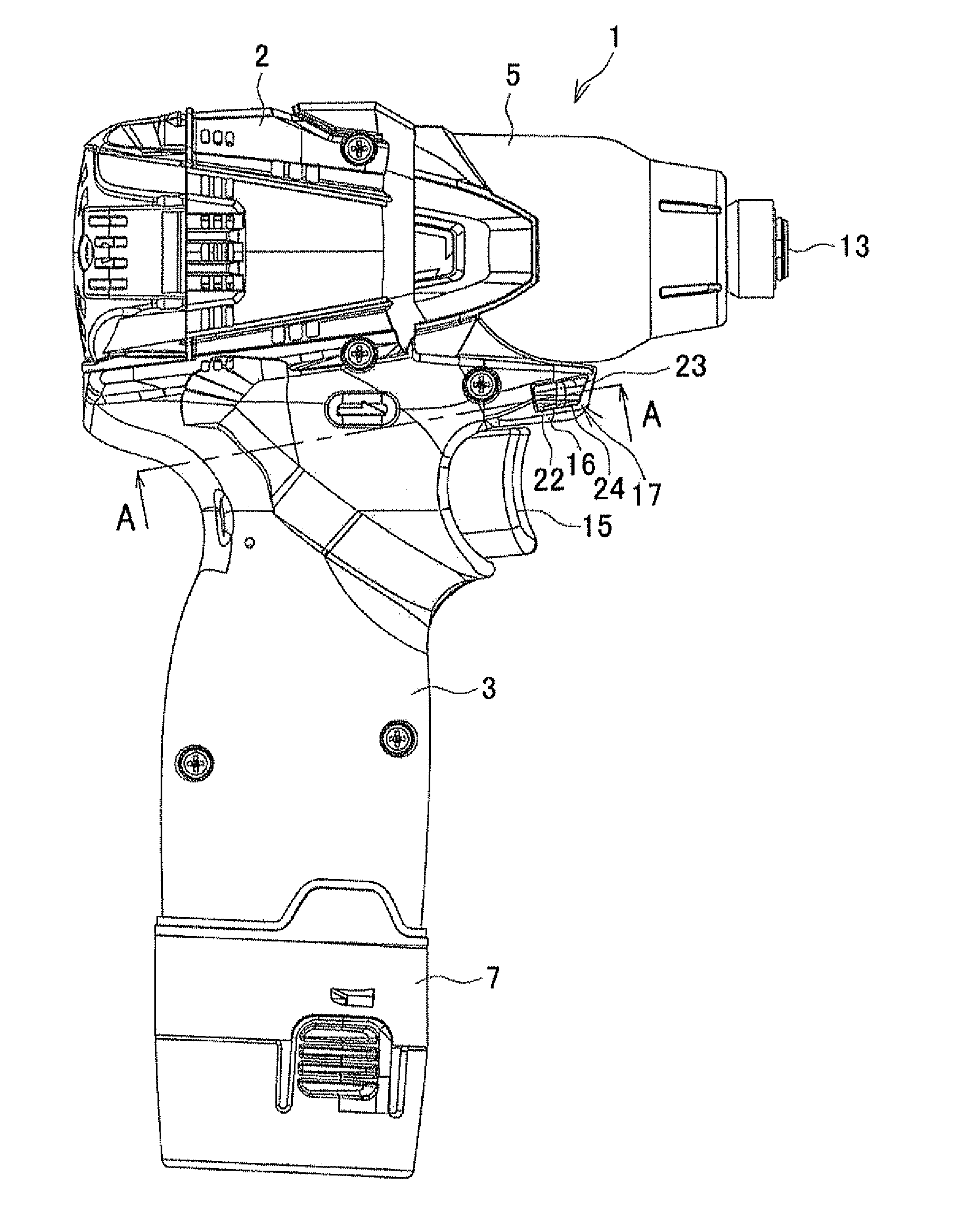
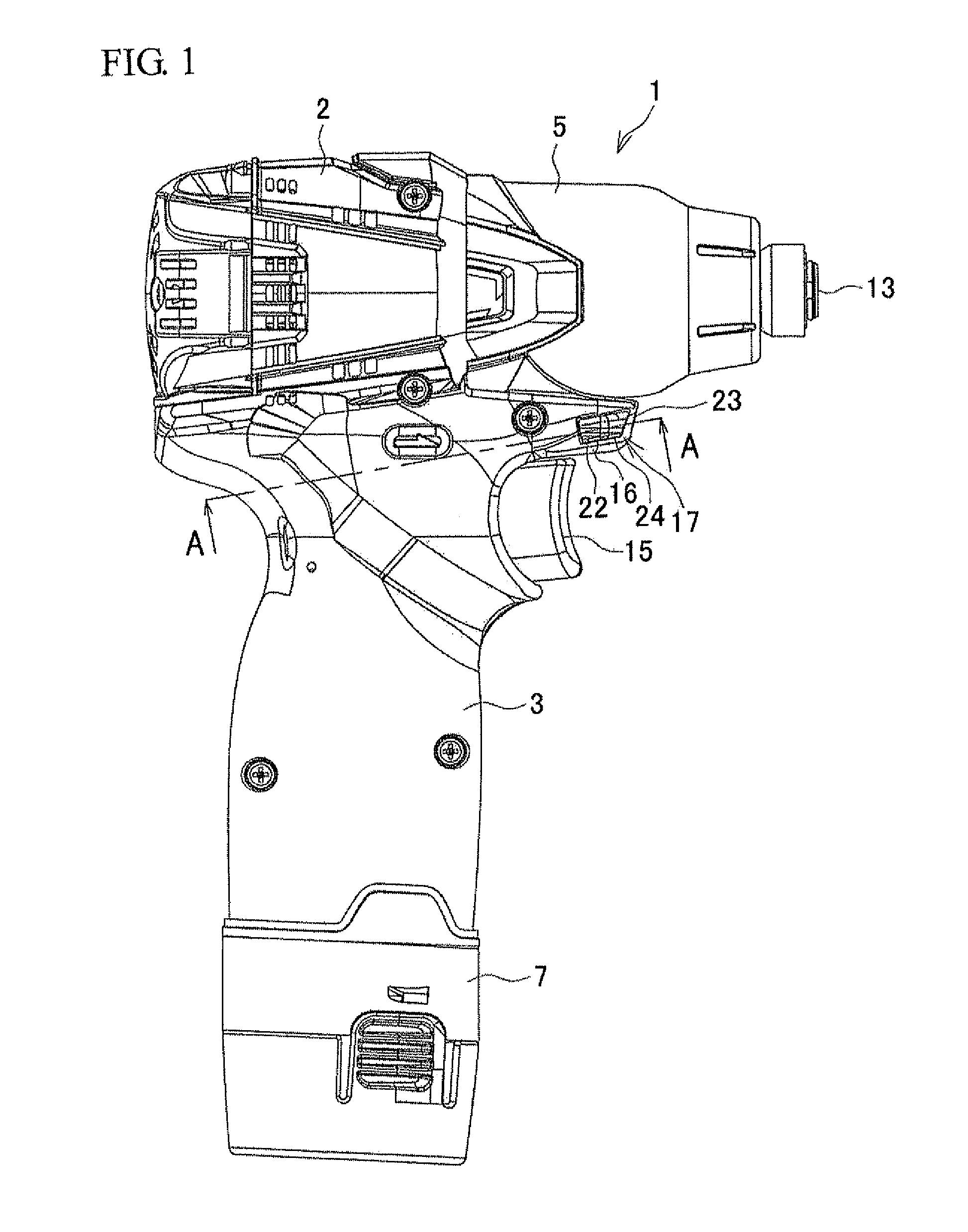
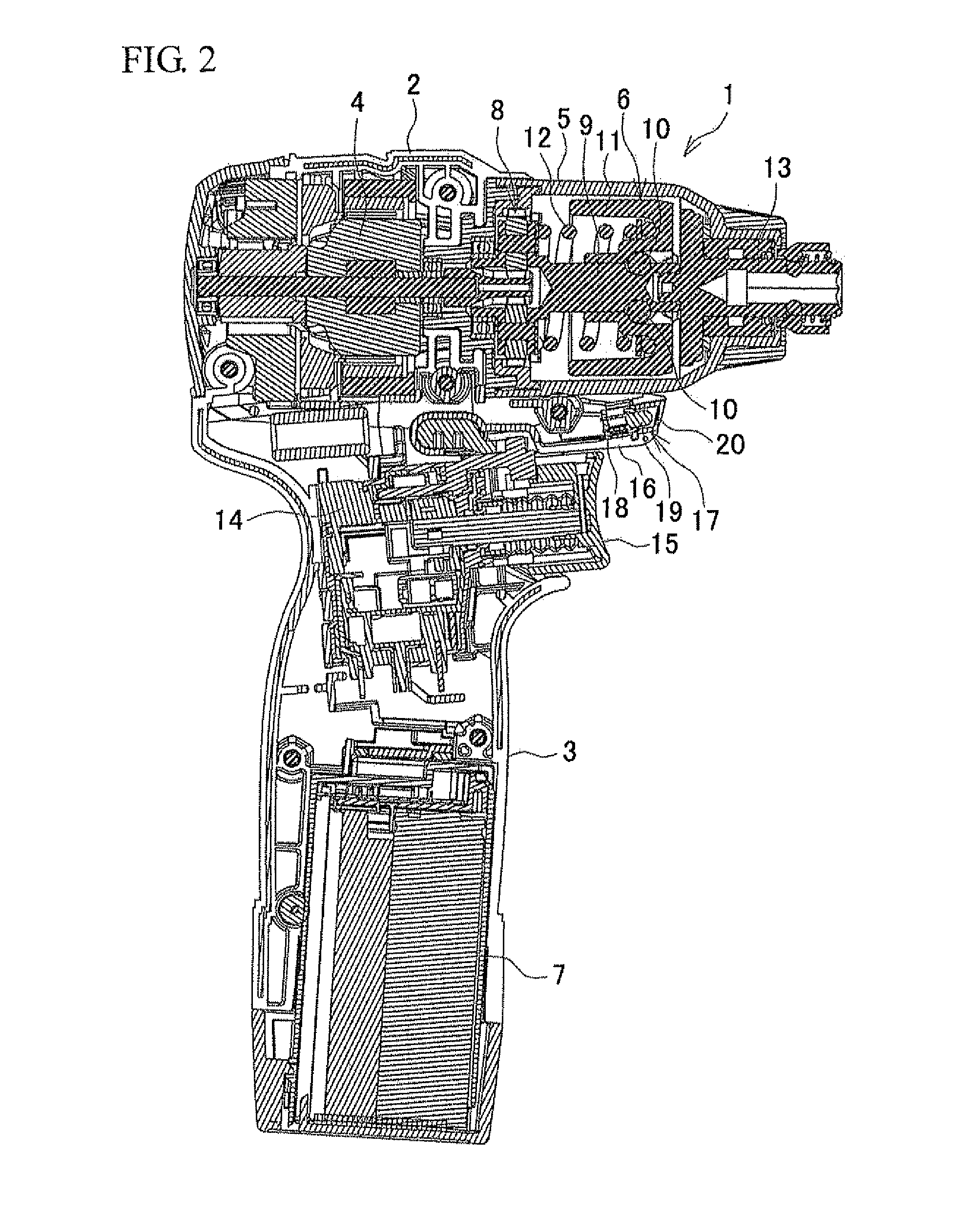
[0025]FIG. 1 is a side view of a rechargeable impact driver I, which is one example of an electric power tool. FIG. 2 is a longitudinal sectional view of the rechargeable impact driver 1. In this rechargeable impact driver 1, a motor 4 is accommodated in an upper rear part (the right side in FIGS. 1 and 2 is assumed to be the front side) of a housing 2, and a handle 3 is provided contiguous to a lower end of the housing 2. A hammer case 5 that accommodates an impact mechanism 6 is connected to a front of the housing 2. A battery pack 7 serving as a power supply is attached to a lower end of the handle 3. The impact mechanism 6 has a well-known configuration. In impact mechanism 6, a hammer 11 is connected, via balls 10, 10, to a spindle 9 to which rotation is transmitted from the motor 4 via a planetary gear speed reduction mechanism 8. Further, in impact mechanism 6, the hammer 11 is engaged,...


PUM


Abstract

In a rechargeable impact driver, a light unit provided in an extension portion of a housing is provided with a substrate, an LED disposed on the substrate so as to face forward, and a lens provided in front of the LED. The LED is used for an illumination function to irradiate ahead of a bit by lighting and for a notification function to notify a decrease in a battery level of a battery pack by flashing.

Description

BACKGROUND OF THE INVENTION[0001]This application claims the benefit of Japanese Patent Application Number 2011-269286 filed on Dec. 8, 2011, the entirety of which is incorporated by reference.TECHNICAL FIELD[0002]The present invention relates to an electric power tool such as a rechargeable impact driver.BACKGROUND ART[0003]In an electric power tool such as a rechargeable impact driver, as disclosed in Japanese Patent Application Publication No. 2007-283447 (JP 2007-283447 A), for example, an LED serving as a light emitter is provided in a housing in a diagonal upward manner. The LED is caused to emit light to irradiate ahead of a bit at the time of driving a motor. On the other hand, an electric circuit substrate is placed at a connection portion of a battery pack formed under a grip section. In this electric circuit substrate, an LED for displaying a fastening speed, a battery level, and the like is incorporated, so that a display of the LED can be checked through a transparent d...

Claims


Application Information

Patent Timeline
IPC IPC(8): B25B23/18
CPCB25F5/021
Inventor MIYAZAWA, MASAMICHI
Owner MAKITA CORP
Why Eureka
Try Eureka