Sonar rendering systems and associated methods

Active Publication Date: 2013-06-13
NAVICO HLDG
View PDF5 Cites 52 Cited by
  • Summary
  • Abstract
  • Description
  • Claims
  • Application Information

AI Technical Summary

Benefits of technology

[0012]FIG. 3 is a block diagram of a more specific example embo

Problems solved by technology

Since the only constant reference for the sonar data is this beam origin, renderings of sonar data can be difficult to interpret.
However, by simply considering the content of the raw sonar data retrieved from a transducer, the physical movement of the waterc

Method used


Image

  • Sonar rendering systems and associated methods
  • Sonar rendering systems and associated methods
  • Sonar rendering systems and associated methods

Examples


Embodiment Construction

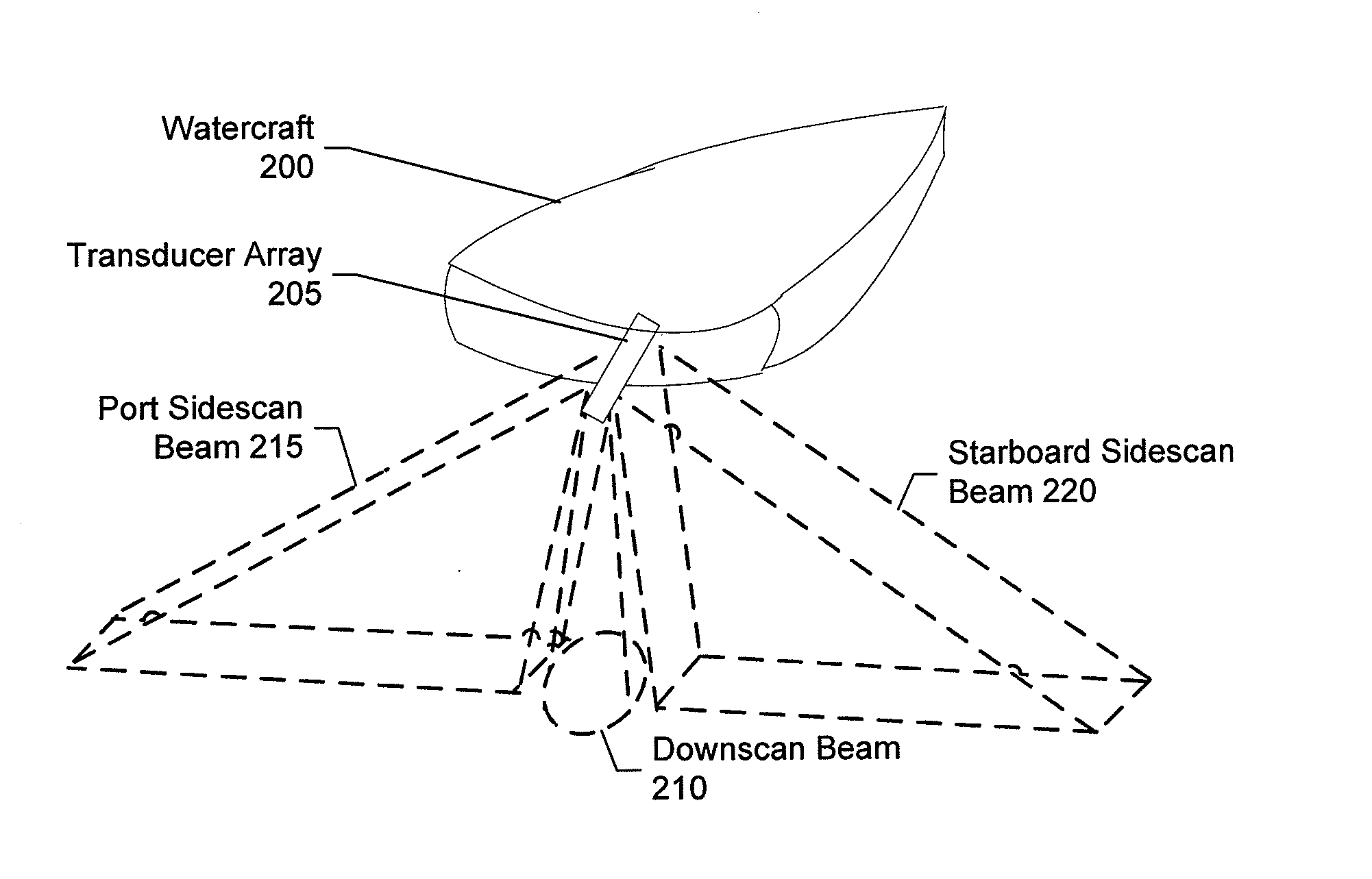
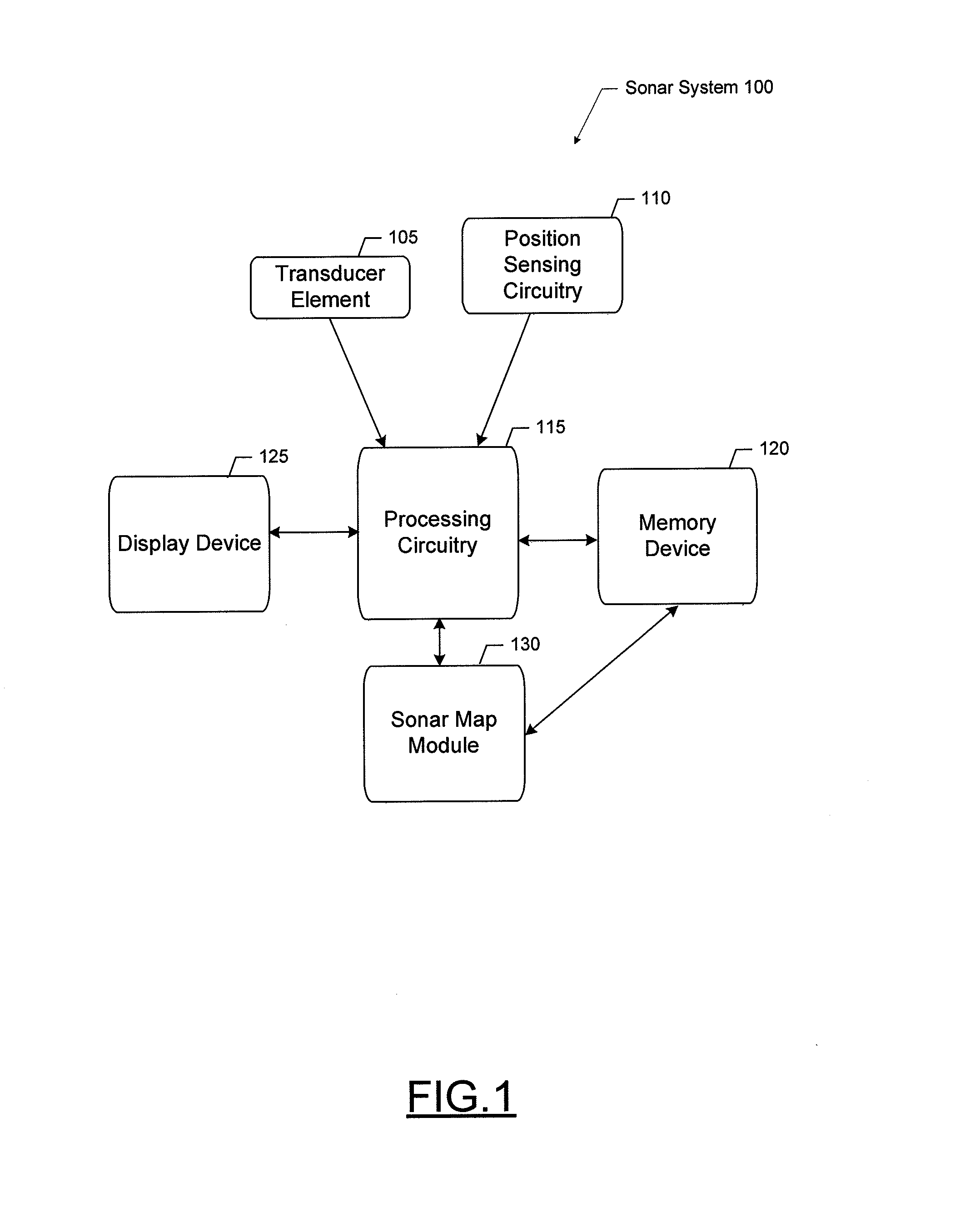
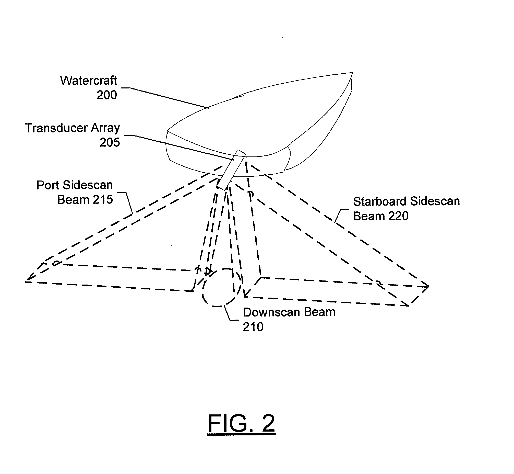
[0006]Example embodiments of various sonar rendering systems and methods are described herein. One example embodiment is an apparatus comprising a transducer assembly, position sensing circuitry, processing circuitry, and a display device. The transducer assembly may be configured to emit a sonar beam, receive return echoes of the sonar beam, and convert the return echoes into raw sonar data. The transducer assembly may also be configured to be affixed to a watercraft. The position sensing circuitry may be configured to determine positioning data. The positioning data may be indicative of a position of the watercraft. The processing circuitry may be configured to receive the raw sonar data and the positioning data, convert the raw sonar data into range cell data based at least on amplitudes of the return echoes, make a location-based association between the raw sonar data and the positioning data, plot the range cell data based on respective positions derived from the positioning da...


PUM


Abstract

Sonar rendering systems and methods are described herein. One example is an apparatus that includes a transducer element, position sensing circuitry, processing circuitry, and a display device. The processing circuitry may be configured to receive raw sonar data and positioning data, convert the raw sonar data into range cell data based at least on amplitudes of the return echoes, make a location-based association between the raw sonar data and the positioning data, plot the range cell data based on respective positions derived from the positioning data and rotate the range cell data based on a direction of movement of the watercraft to generate adjusted range cell data. The processing circuitry may be further configured to convert the adjusted range cell data into sonar image data, and cause the display device to render the sonar image data with a presentation of a geographic map.

Description

FIELD OF THE INVENTION[0001]Embodiments of the present invention relate generally to sonar systems, and more particularly, to managing and rendering sonar data.BACKGROUND OF THE INVENTION[0002]Sonar has long been used to detect waterborne or underwater objects. Sonar devices may be used to determine depth and bottom topography, detect fish or other waterborne objects, locate wreckage, etc. In this regard, due to the extreme limits on underwater visibility, sonar is typically the most accurate way to locate objects underwater. Devices such as transducer elements, or simply transducers, have been developed to produce sound or vibrations at a particular frequency that is transmitted into and through the water. Echo returns from the transmitted sound reflected off an object are received, either by the same transducers or by separate receiver elements and are converted into an electrical signal. These electrical signals can be analyzed and interpreted to obtain information about underwat...

Claims


Application Information

Patent Timeline
IPC IPC(8): G01S15/89G01S15/86
CPCG01S15/8902G01S7/6281G01S15/50G01S15/025G01S7/629G01S15/86
Inventor BROWN, KEVINCOLEMAN, AARON
Owner NAVICO HLDG
Why Eureka
Try Eureka