Low center of gravity carrier

a carrier and center of gravity technology, applied in the direction of transportation and packaging, loading/unloading vehicle arrangment, transportation items, etc., can solve the problem that the super single wheel configuration is not available on light-duty and medium-duty chassis, and achieve the effect of reducing the load angle of the platform, lowering the platform height, and increasing the payload heigh

Active Publication Date: 2013-06-13
MILLER IND TOWING EQUIP INC
View PDF5 Cites 10 Cited by
  • Summary
  • Abstract
  • Description
  • Claims
  • Application Information

AI Technical Summary

Benefits of technology

[0019]In another preferred embodiment of the invention, a carrier is provided having a vehicle chassis with frame rails and rear wheels supported by a rear axle suspension. The carrier includes a subframe with rails interposed between the frame rails and the rear wheels of the vehicle chassis. The subframe is preferably tiltable relative to the vehicle chassis. A platform may be mounted to the subframe; the platform may be slidable in a generally horizontal direction relative to the subframe. Subframe rails are preferably interposed between the frame rails of the vehicle chassis and the rear wheels, enabling a lowered platform height and an increase in the payload height in comparison to conventional carrier...

Problems solved by technology

The Super Single wheel configuration is not curr...

Method used


Image

  • Low center of gravity carrier
  • Low center of gravity carrier
  • Low center of gravity carrier

Examples


Embodiment Construction

[0076]Set forth below is a description of what are believed to be the preferred embodiments and / or best examples of the invention claimed. Future and present alternatives and modifications to this preferred embodiment are contemplated. Any alternatives or modifications which make insubstantial changes in function, in purpose, in structure, or in result are intended to be covered by the claims of this patent.

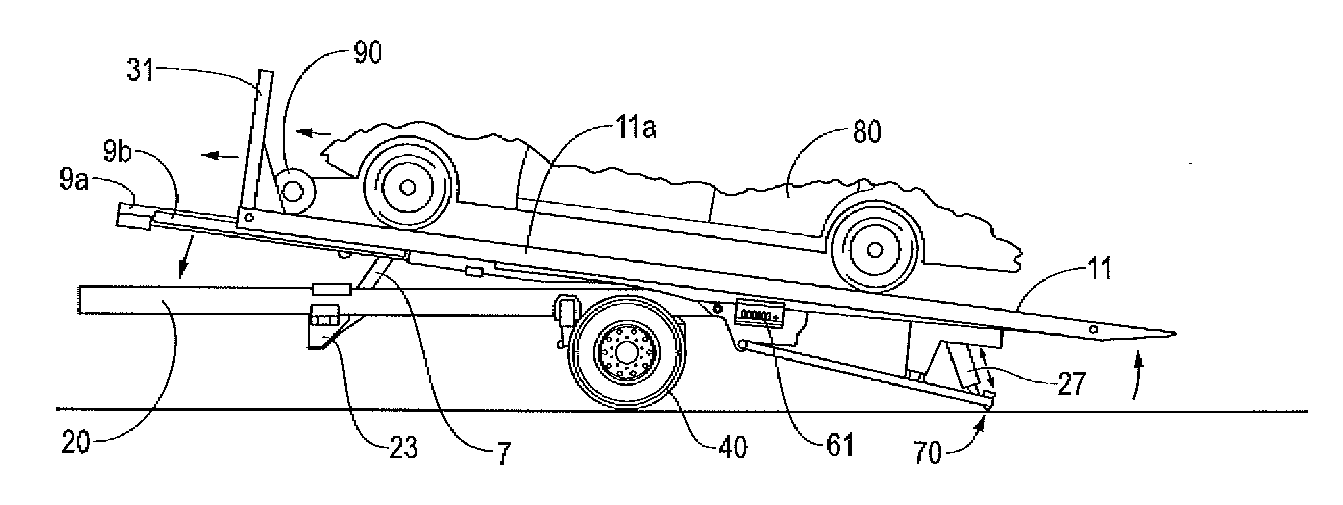
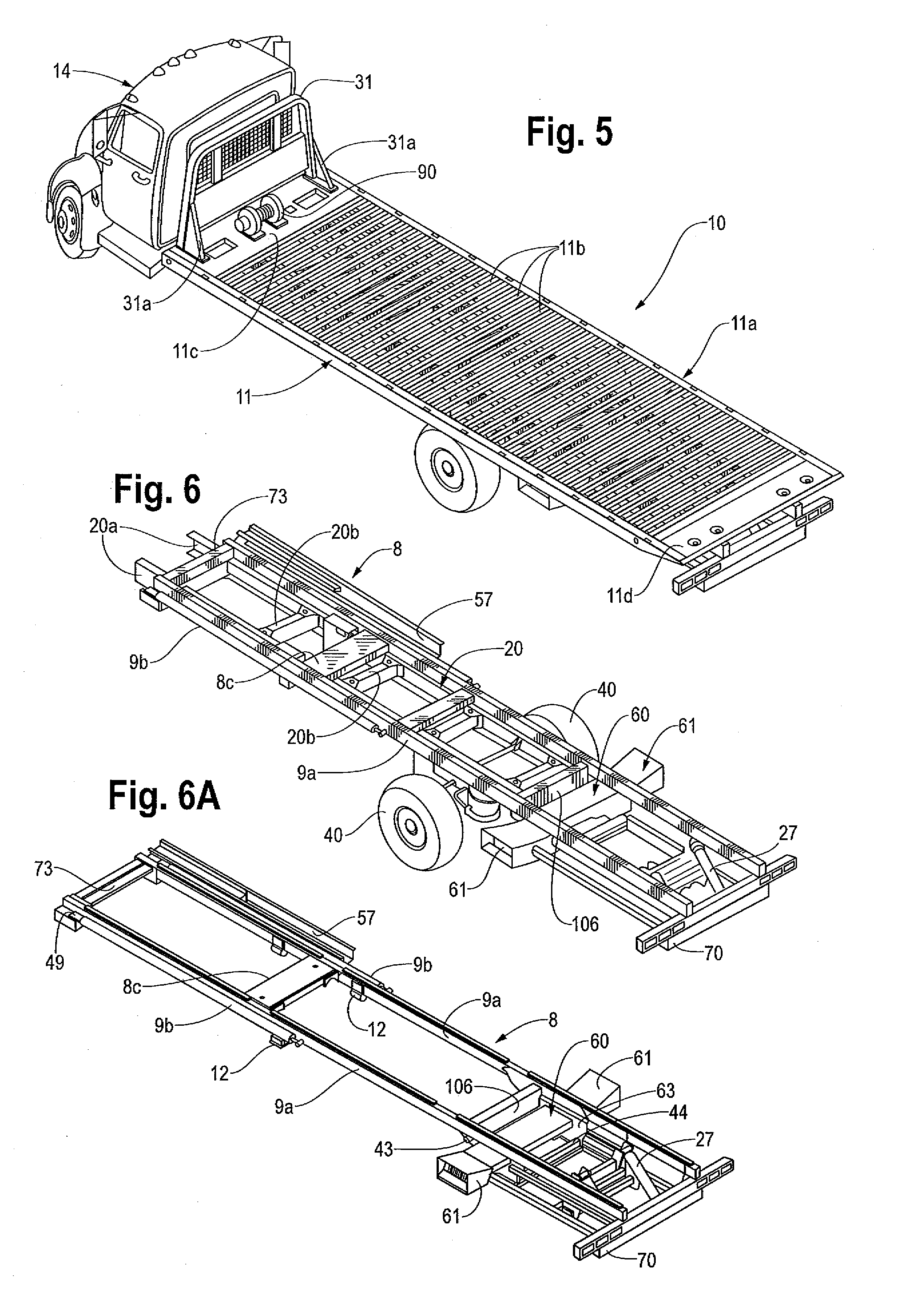
[0077]Referring first to FIGS. 5, 6 and 6A, a preferred embodiment of carrier 10 includes vehicle cab 14 pulling slidable and tiltable platform 11. Rear of the cab, cab protector bar 31 may be supported on platform 11 by weldments 31 a on the platform. Platform 11 may be supported by subframe 8, which may be positioned adjacent to and attached to vehicle chassis 20 as explained below.

[0078]Referring to FIGS. 5-6, vehicle chassis 20 may include opposing longitudinal chassis rails 20a, supported by chassis crossmembers 20b. Super Single rear wheels 40 may be mounted as shown. Subfr...


PUM


Abstract

A carrier having a platform or deck mounted on a subframe tiltable relative to the vehicle chassis. The platform is preferably slidable relative to the subframe. Sufficient clearance is provided such that the subframe is preferably located between the vehicle chassis frame and the rear wheels, and below the top of the chassis frame. The resulting carrier has a platform with a height substantially lower than that of previous carriers, providing it with a lower center of gravity, enabling a reduction in load angle, an increase in payload height, and enhanced dynamic road stability.

Description

RELATED PATENTS[0001]This application is a continuation of U.S. Ser. No. 12 / 612,756, for which a Notice of Allowance issued on Nov. 2, 2012, which is a continuation-in-part of U.S. Pat. No. 8,070,411 (“the parent case”) issued on Dec. 6, 2011 and titled “Low Center Of Gravity Carrier” for claims 1-5, 8-16, 19 and 20. This continuation application contains no new matter.[0002]U.S. Pat. No. 5,061,147 filed Oct. 29, 1991 and titled “Vehicle Carrier with Wheel Lift” is hereby incorporated by reference in its entirety into this disclosure.BACKGROUND OF THE INVENTION[0003]The present invention generally relates to tilting bed carriers. More specifically, the invention is directed to the art of tilting bed carriers using a tilting platform having a low center of gravity and relatively small loading angle.[0004]Various carriers, including car carriers as well as industrial carriers (for carrying forklifts, tractors and machines, etc.), are known, as shown in U.S. Pat. No. 4,750,856 ('856 pa...

Claims


Application Information

Patent Timeline
IPC IPC(8): B60P1/04
CPCB60P3/122B60P1/04B60P1/045B60P1/16B60P1/32B60P3/07
Inventor JAEGER, DAVIDNESPOR, RONALD B.
Owner MILLER IND TOWING EQUIP INC
Why Eureka
Try Eureka