

Powered Lower Extremity Orthotic and Method of Operation
a technology of lower extremity and operation method, which is applied in the field of controlling the trajectory of artificial feet, can solve the problems that the fluid system control is also needed, and achieve the effect of reducing the necessary hip torque and power, less electric power, and efficient creation
- Summary
- Abstract
- Description
- Claims
- Application Information
AI Technical Summary
Benefits of technology
Problems solved by technology
Method used
Image

Examples
Embodiment Construction
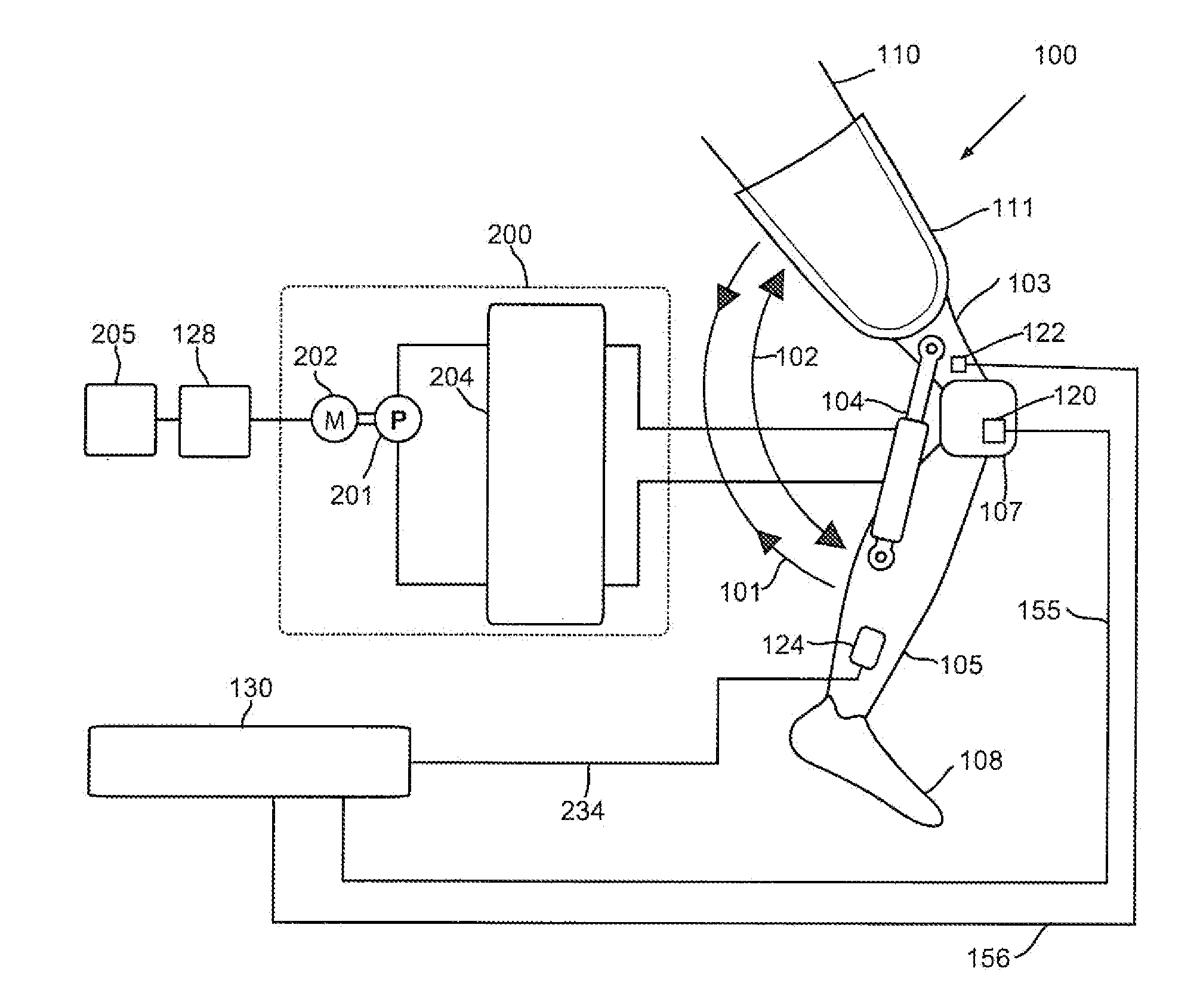
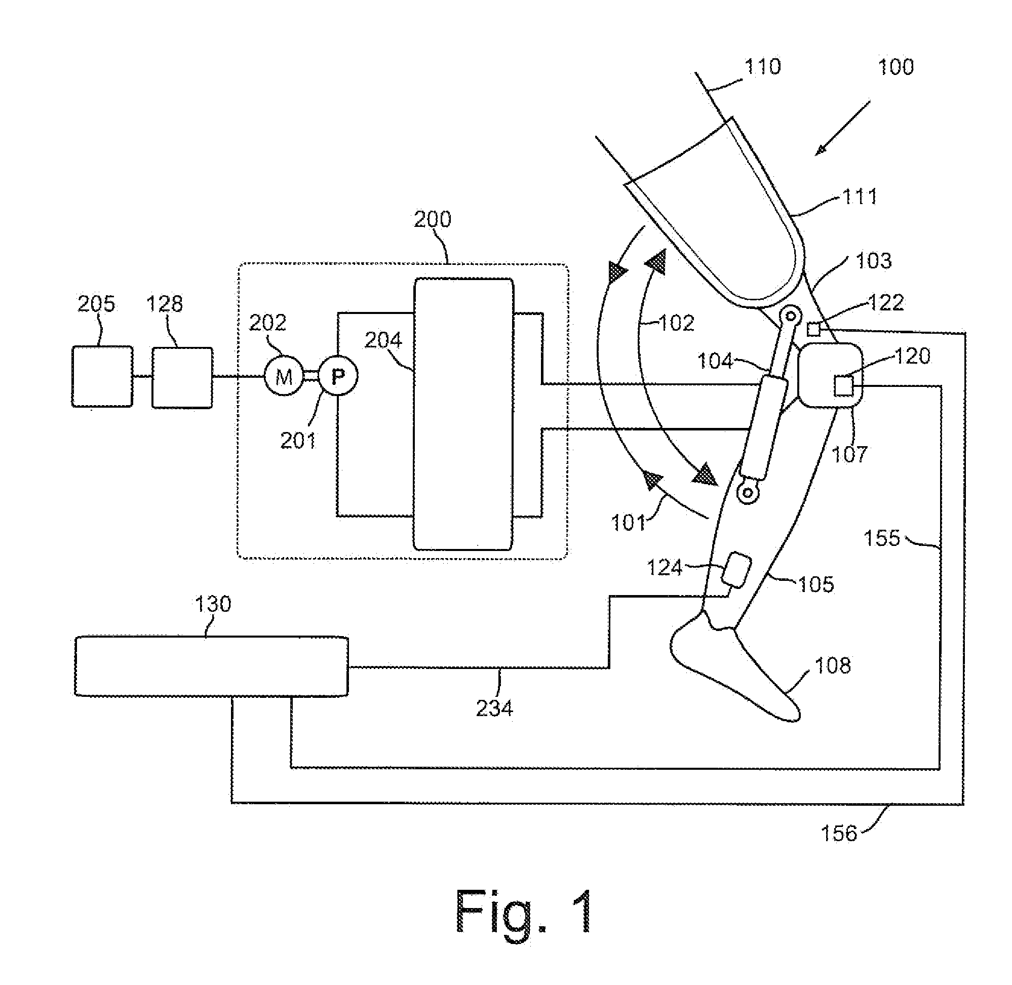
[0058]With initial reference to FIG. 1, a semi-actuated prosthetic knee 100 constructed in accordance with a first embodiment of the invention is configurable to be coupled to an above-knee amputee's remaining lower limb 110 through a socket 111. Semi-actuated prosthetic knee 100, among other components, comprises a thigh link 103 coupled to a knee mechanism 107 and a shank link 105 coupled to an artificial foot 108. Knee mechanism 107 is configured to allow flexion and extension movements of thigh link 103 and a shank link 105 relative to each other along flexion direction 101 and extension direction 102. A hydraulic torque generator 104 is configured to generate torque between thigh link, 103 and shank link 105.
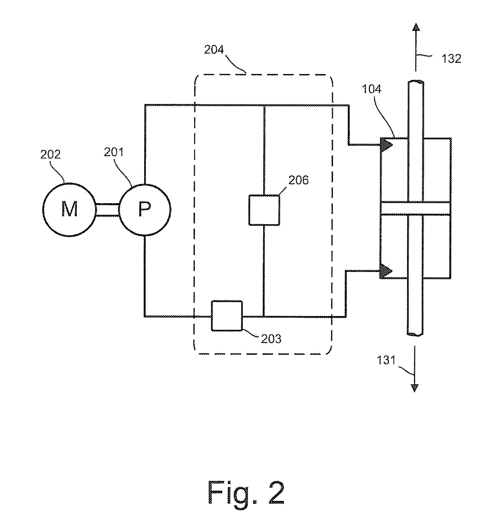
[0059]Semi-actuated prosthetic knee 100 further includes a hydraulic power unit indicated at 200 coupled to hydraulic torque generator 104. Hydraulic power unit 200, among other components, includes a hydraulic valve circuit 204, which is hydraulically coupled to torque gen...
PUM
 Abstract
Description
Claims
Application Information