
Prosthetic limb

a technology for prosthetic limbs and limbs, applied in the field of prosthetic limbs, can solve the problems of not readily available to people, little thought given to the aesthetics of the human being for whom the device was intended, and many people do not have access to prosthetic limb manufacturers, etc., to achieve the effect of reducing rotational friction due to sliding components, reducing friction, and running more efficiently

Inactive Publication Date: 2013-06-13
3D SYST INC
View PDF5 Cites 9 Cited by
  • Summary
  • Abstract
  • Description
  • Claims
  • Application Information

AI Technical Summary

Benefits of technology

The solution provides a cost-effective, durable, and functional prosthetic limb that mimics natural leg movement, ensuring stability and mobility while being accessible for remote users through digital design and remote fabrication.

Problems solved by technology

While the engineering and mechanics of prosthetic limbs have evolved greatly, very little thought has been given to the aesthetics of the human being for whom the device was intended.
A problem with the existing prosthetic limbs is that they are not readily available to people who live in remote parts of the world.
Many of these people do not have access to prosthetic limb manufacturers.
Also, since prosthetic limbs are very expensive, many people do not have the financial resources to purchase them.
Without these resources, the amputees cannot obtain properly designed prosthetic limbs and may rely upon other devices for mobility such as crutches or wheelchairs.
While this does allow upper and lower leg to rotate similar to a human leg, the knee does not lock out with each stride, increasing the risk of a fall or uncertain step.
While these devices provide basic mobility, they are not as practical as prosthetic limbs since they require the use of arms.
Thus, the user cannot use his or her arms while moving.

Method used


Image

  • Prosthetic limb
  • Prosthetic limb
  • Prosthetic limb

Examples


Embodiment Construction

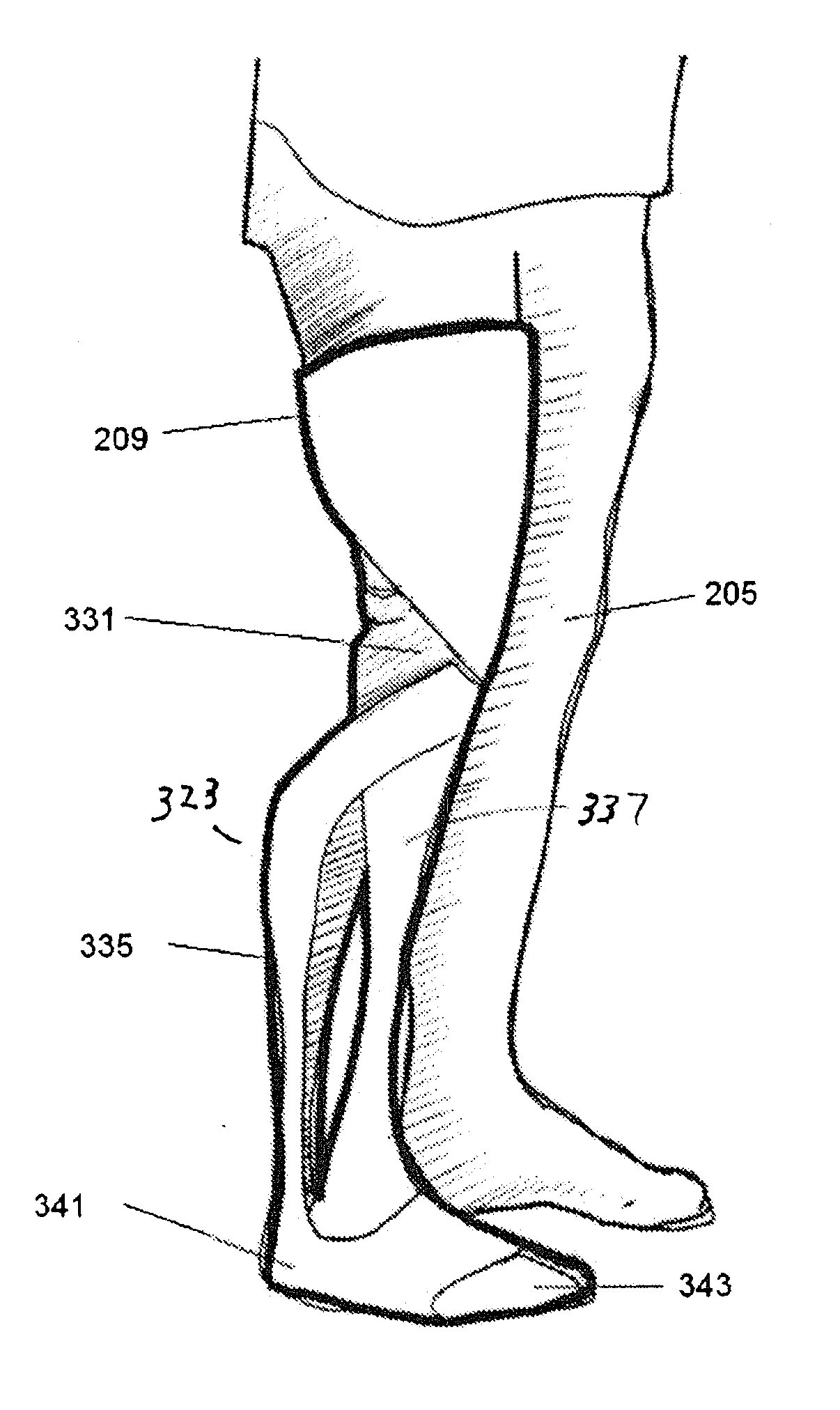
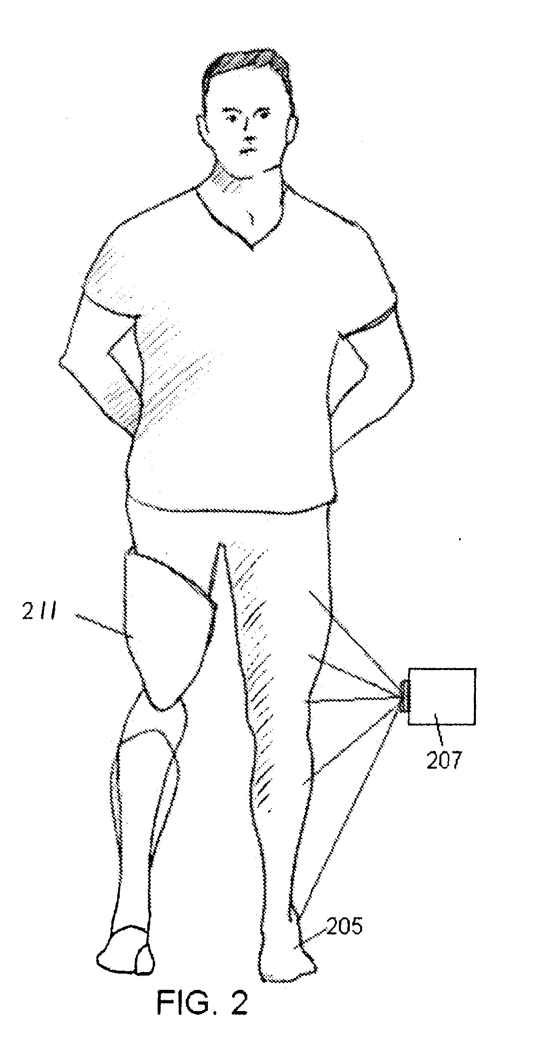
[0036]The present invention is a custom designed prosthetic limb having an integrated construction. The inventive prosthetic limb is primarily directed towards prosthetic legs but the same design and fabrication processes can also be used to create prosthetic arms. The prosthetic limb is preferably designed by an industrial designer using a Computer Aided Design (CAD) program.

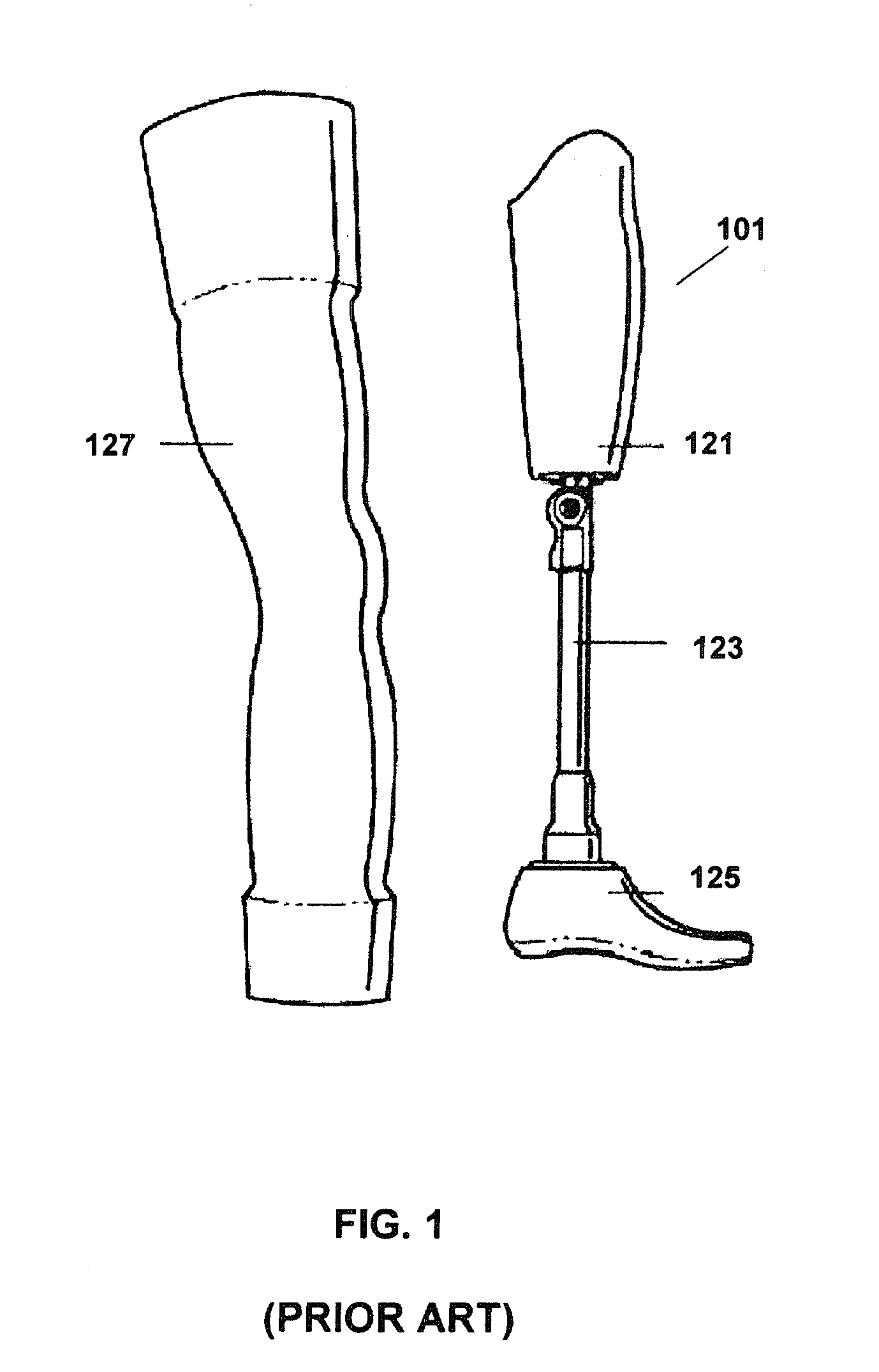
[0037]In an embodiment, the inventive prosthetic leg includes a load bearing component that functions as the human femur, knee, tibia and foot. The upper leg of the load bearing component is attached to a socket that engages the end of the amputated limb. The lower end of the upper leg and the upper end of the lower leg are coupled to the artificial knee. The lower end of the lower leg is coupled to an artificial foot. The mechanical data for the prosthetic leg may include the relative positions of the socket, knee and foot as well as the movement of these components based upon geometry and movement of the inta...


PUM


Abstract

A prosthetic limb has an outer surface that is a mirror image of an intact limb or a generic limb design. The intact limb is scanned and the surface data is manipulated to create a virtual mirror image. If generic data is used, the intact leg can be measured and the generic surface can be adjusted so the prosthetic limb appears similar to the intact limb. The end of the amputated limb is also measured to obtain socket data. A knee and foot are incorporated to form a virtual prosthetic limb represented by design data. The design data for the virtual prosthetic limb is forwarded to a rapid prototyping machine that fabricates the entire leg simultaneously. Once completed, the prosthetic limb is shipped to the patient.

Description

CROSS REFERENCE TO RELATED APPLICATIONS[0001]This application is a continuation of U.S. patent application Ser. No. 12 / 128,378, “Prosthetic Limb” filed May 28, 2008, which is now U.S. Pat. No. 8,366,789, the contents of which are hereby incorporated by reference in its entirety.BACKGROUND[0002]A prosthesis limb replaces a missing extremity, such as an arm or a leg and may be needed for a variety of reasons, including diseases, and accidents. An artificial limb may also be needed when a person is born with a missing or damaged limb(s). The type of prosthesis limb used is determined largely by the extent of an amputation or loss and location of the missing limb. A transtibial prosthesis is an artificial leg that is attached to a user below the knee and includes a lower leg, ankle and foot. The transfemoral prosthesis is an artificial leg that is attached to the user's amputated limb above the knee and includes an upper leg and mechanical knee. A transradial prosthesis is an artificial...

Claims


Application Information

Patent Timeline
Patent Type & Authority Applications(United States)
IPC IPC(8): A61F2/60A61F2/66A61F2/78
CPCA61F2/5046A61F2/7812A61F2/64A61F2/644A61F2/6607A61F2/80A61F2002/30426A61F2002/5043A61F2002/5047A61F2002/5049A61F2002/505A61F2002/5056A61F2002/5069A61F2002/507A61F2002/5079A61F2002/509A61F2002/5098A61F2002/607A61F2002/608A61F2002/6614A61F2002/6621A61F2002/6854A61F2220/0025A61F2/66A61F2/60B33Y80/00
Inventor SUMMIT, SCOTT
Owner 3D SYST INC
Learn More