
Distillation apparatus

Inactive Publication Date: 2013-06-20
HANS HEIDOLPH
View PDF6 Cites 14 Cited by
  • Summary
  • Abstract
  • Description
  • Claims
  • Application Information

AI Technical Summary

Benefits of technology

This patent describes a distillation apparatus that allows for quick production of larger quantities of distillate or residue. The apparatus is automated, so the emptying of the distillation vessel is no longer a manual task. The removal of the residue is also automated, so start and triggering of the removal process can be done without having to release the vessel from the apparatus. The removal device includes a suction line and optionally a suction pump or valve to prevent distillation residue from flowing back into the distillation vessel. Overall, this patent describes a more efficient and automated process for producing distillate and residue.

Problems solved by technology

This is time-consuming.

Method used


Image

  • Distillation apparatus
  • Distillation apparatus

Examples


Embodiment Construction

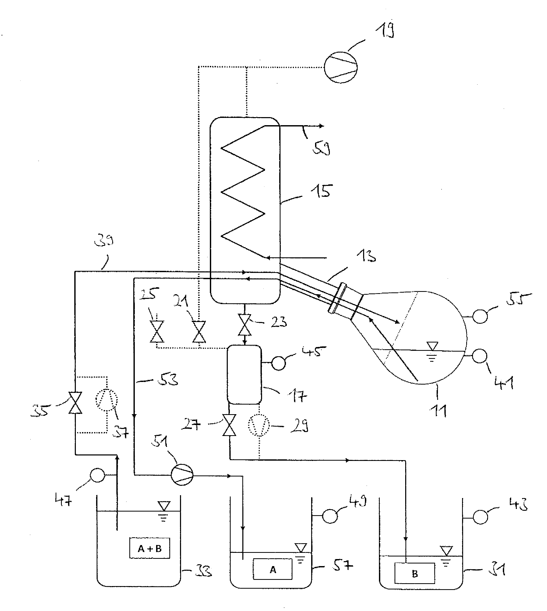
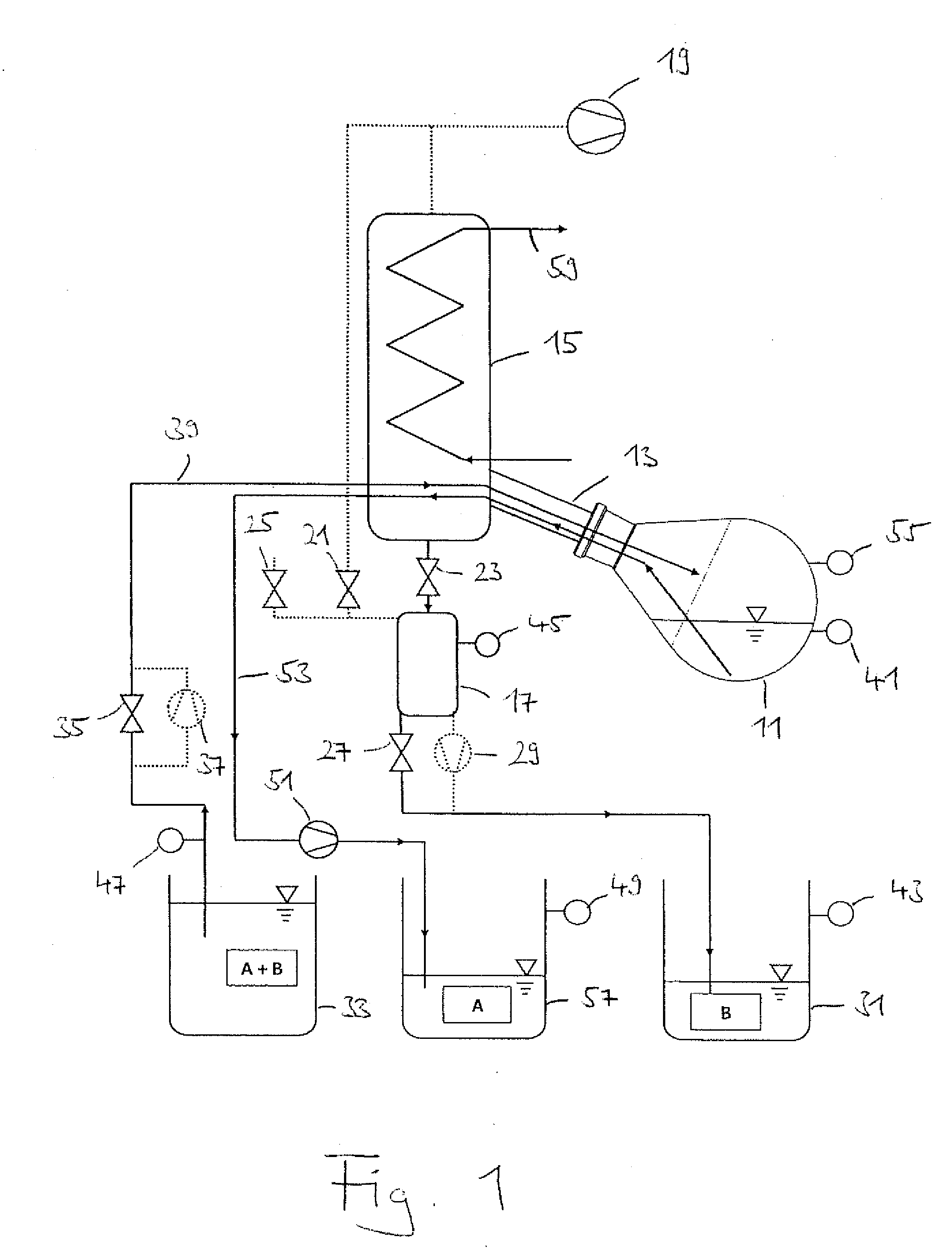
[0028]The laboratory rotary evaporator shown in FIG. 1 includes a rotary drive, not shown, for an evaporator flask 11 which is designed as a round bottomed flask or a V-shaped flask or the like and which can be heated in a heating bath, not shown, to evaporate a distillate from a liquid mixture present therein. The evaporated distillate then moves via a vapor passage 13 led through the rotary drive into a condenser 15 which is flowed through by a cooling medium 59 to condense there. Subsequently, the condensed distillate is collected in a collecting flask 17, with a valve 23 being provided between the condenser 15 and the collecting flask 17. The distillation residue remaining in the evaporator flask 11 can be further processed or analyzed.

[0029]Furthermore, a vacuum pump 19 is provided to apply a partial vacuum to the condenser 15 and thus to the evaporation flask 11 as well as additionally also—via an evacuation valve 21—optionally to the collecting flask 17, whereby the boiling t...


PUM


Abstract

The invention relates to a distillation apparatus, in particular a distillation apparatus configured as a piece of laboratory equipment, having a distillation vessel for receiving a mixture to be distilled, wherein a removal device is provided which is configured for the automated removal of a distillation residue from the distillation vessel.

Description

CROSS-REFERENCE TO RELATED APPLICATIONS[0001]This application claims priority of German Patent Application DE 102011121650.6 filed Dec. 19, 2011.FIELD OF THE INVENTION[0002]The present invention relates to a distillation apparatus, in particular to a distillation apparatus configured as a piece of laboratory equipment, having a distillation vessel for receiving a mixture to be distilled.BACKGROUND OF THE INVENTION[0003]Distillation apparatus are known from the prior art in which the distillation takes place in batch operation. In this respect, the distillation vessel is first filled with the starting materials. The distillation then takes place, i.e. the mixture is separated by thermal evaporation and subsequent condensation of at least one of the starting materials into a distillate or condensate, on the one hand, and into a residue remaining in the distillation vessel, on the other hand. The distillation vessel is then removed from the total apparatus and emptied by pouring out th...

Claims


Application Information

Patent Timeline
IPC IPC(8): B01D3/00
CPCB01D3/085B01D3/00B01D3/42B01D3/108
Inventor CARL, JOACHIMNICO, PATRICKZEHNDER, JOCHEN
Owner HANS HEIDOLPH
Learn More