Method and system for coordinating collisions between augmented reality and real reality

a collision and augmented reality technology, applied in the field of methods and systems for coordinating collisions between augmented reality and real reality, can solve the problems of mismatch between actions in the real world environment and the virtual reality object is not the same, and achieve the effect of smoother and intuitive connection

Inactive Publication Date: 2013-06-20
XEROX CORP
View PDF6 Cites 49 Cited by
  • Summary
  • Abstract
  • Description
  • Claims
  • Application Information

AI Technical Summary

Benefits of technology

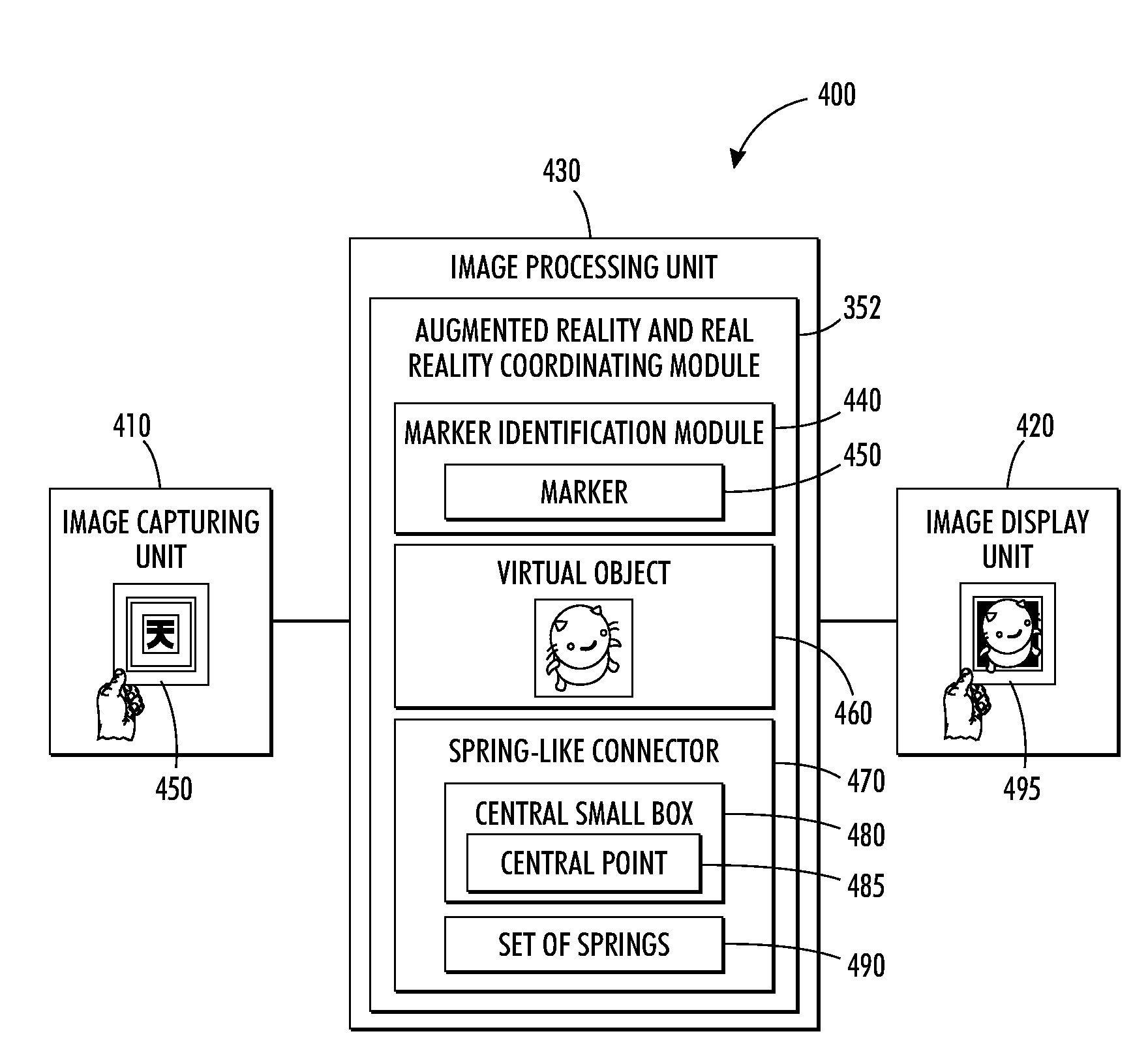
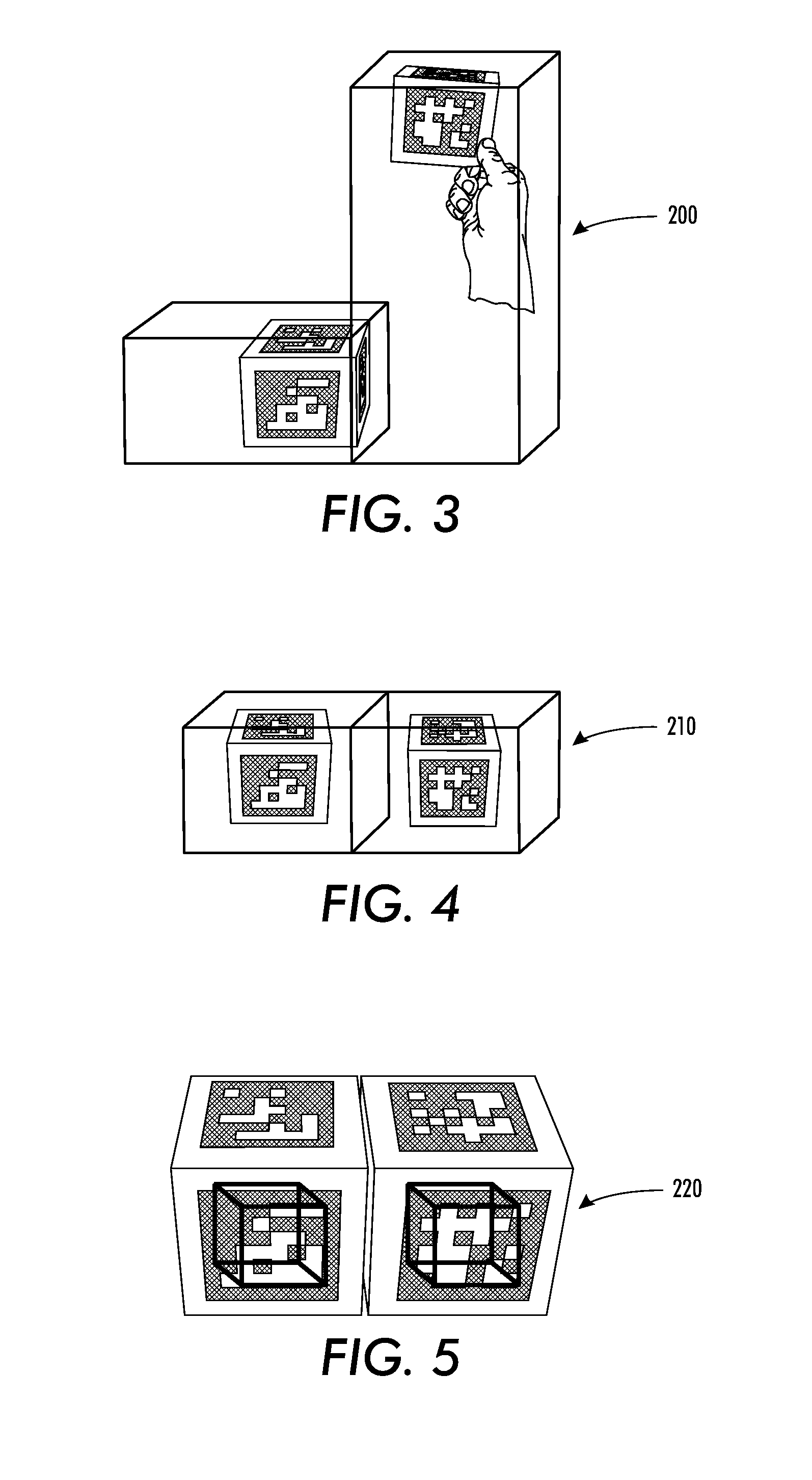
[0010]The aforementioned aspects and other objectives and advantages can now be achieved as described herein. A method and system for coordinating placement of an augmented reality/virtual world object(s) into a scene relative to position and orientation of a marker is disclosed herein. The object(s) can be connected to an anchor point having an absolute location relative to the marker via a connector (e.g., spring-like connector) in such a way that the behavior of the object can respond to a physical force and collision which exist in the augmented reality scene. The connection between the virtual object and location of the marker permits the object to exactly track the marker when there are no real world collisions between the markers. The virtual objects can be displaced so the objects do not pass through one another when the real world markers come into a close spatial proximity and the corresponding virtual objects begin to collide. The object can track the marker in a loosely coupled fashion thereby permitting a smoother and more intuitive connection between the motion of the marker and the object.
[0011]An image capturing unit

Problems solved by technology

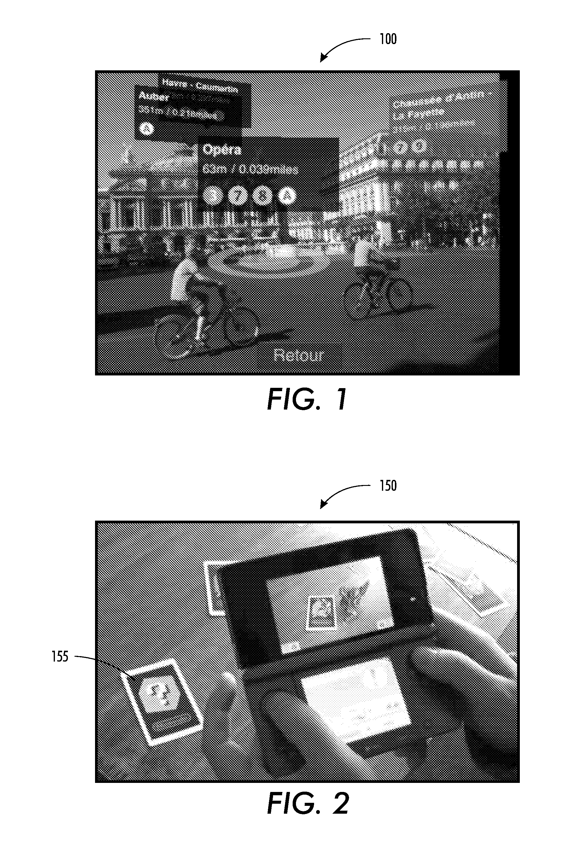
One of the problems associated with such prior art system 150 is that the virtual reality object is not the same size and shape as the augmented reality marke

Method used


Image

  • Method and system for coordinating collisions between augmented reality and real reality
  • Method and system for coordinating collisions between augmented reality and real reality
  • Method and system for coordinating collisions between augmented reality and real reality

Examples


Embodiment Construction

[0024]The particular values and configurations discussed in these non-limiting examples can be varied and are cited merely to illustrate at least one embodiment and are not intended to limit the scope thereof.

[0025]The embodiments will now be described more fully hereinafter with reference to the accompanying drawings, in which illustrative embodiments of the invention are shown. The embodiments disclosed herein can be embodied in many different forms and should not be construed as limited to the embodiments set forth herein; rather, these embodiments are provided so that this disclosure will be thorough and complete and will fully convey the scope of the invention to those skilled in the art. Like numbers refer to like elements throughout. As used herein, the term “and / or” includes any and all combinations of one or more of the associated listed items.

[0026]The terminology used herein is for the purpose of describing particular embodiments only and is not intended to be limiting of...


PUM


Abstract

A method and system for coordinating placement of an augmented reality/virtual world object(s) into a scene relative to position and orientation. The object(s) can be connected to an anchor point having an absolute location relative to the marker via a connector (e.g., spring-like connector) in such a way that the behavior of the object responds to a physical force and a collision which exists in the augmented reality scene. The connection between the virtual object and location of the marker permits the object to exactly track the marker when there are no real world collisions between the markers. The virtual objects can be displaced so the objects do not pass through one another when the real world markers come into a close spatial proximity and the corresponding virtual objects begin to collide.

Description

TECHNICAL FIELD[0001]Embodiments are generally related to AR (Augmented Reality). Embodiments are also related to the interaction between augmented reality and real reality. Embodiments are additionally related to coordinating collisions between augmented reality and real reality.BACKGROUND OF THE INVENTION[0002]AR (Augmented Reality) is a term for a live direct or indirect view of a physical, real-world environment whose elements are augmented by a computer-generated sensory input such as, for example, sound, video, graphics or GPS (Global Positioning System) data. Augmented reality is generally related to mediated reality, in which a view of reality is modified (possibly even diminished rather than augmented) by a computer. As a result, the technology functions by enhancing one's current perception of reality. By contrast, virtual reality (VR) replaces the real world with a simulated one. Augmented reality is considered as an extension of virtual reality. Virtual reality is a virt...

Claims


Application Information

Patent Timeline
IPC IPC(8): G09G5/00
CPCG06T2210/21G06T19/006
Inventor ROLLESTON, ROBERT JOHNKINGSIEY, JEFFREY DAVIDWANG, JIA
Owner XEROX CORP
Why Eureka
Try Eureka