
System and method for enabling users to interact in a virtual space

a virtual space and user technology, applied in the field of packet communication, can solve the problems of not all network topologies can handle broadcasts, communication is much more difficult, and the architecture is further limited

Inactive Publication Date: 2007-03-01
WORLDS
View PDF15 Cites 202 Cited by
  • Summary
  • Abstract
  • Description
  • Claims
  • Application Information

AI Technical Summary

Benefits of technology

"The present invention is a system for creating a virtual world where multiple users can interact and view objects from different perspectives. The system uses motion information to update the view of the user's avatars and a database to determine which objects to render and which to limit the movement of the avatar. The technical effect of this invention is a highly scalable and immersive virtual world where users can interact and view objects from different angles."

Problems solved by technology

However, where many client machines or processes are communicating with each other in real-time through the server, several problems arise.
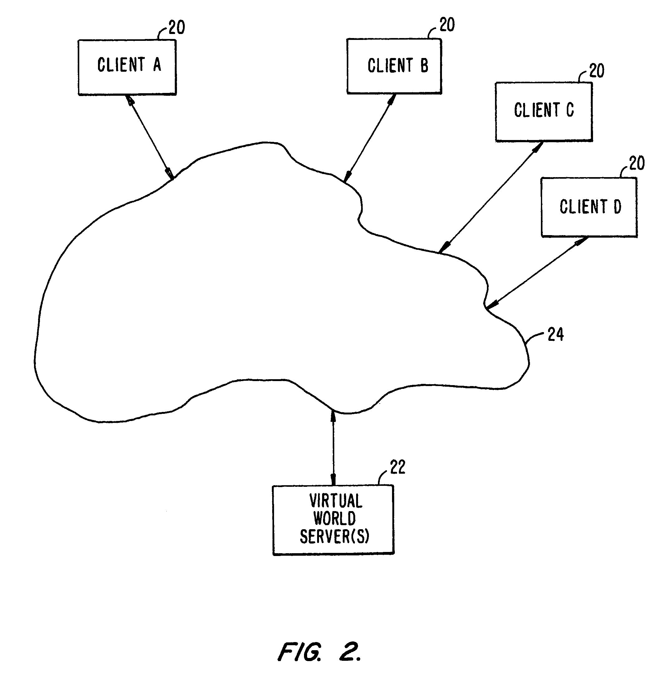
For example, where a client-server system is used for real-time exchange of information, such as a distributed virtual reality network where users at client machines visually and aurally interact with other users at other client machines, communication is much more difficult, especially where the information is high-bandwidth data such as audio streams, graphic images and image streams.
With true broadcasting, one message is sent and all clients listen for it, but not all network topologies can handle broadcasts.
This architecture is further limited where the network is not a dedicated network, but is an open network, such as the Internet.
With Internet communications, true broadcasting is not even possible because the network's extent is not known or fixed.
An additional problem with Internet communications is that packet delivery is not guaranteed nor is it even as reliable as a dedicated network.

Method used


Image

  • System and method for enabling users to interact in a virtual space
  • System and method for enabling users to interact in a virtual space
  • System and method for enabling users to interact in a virtual space

Examples


Embodiment Construction

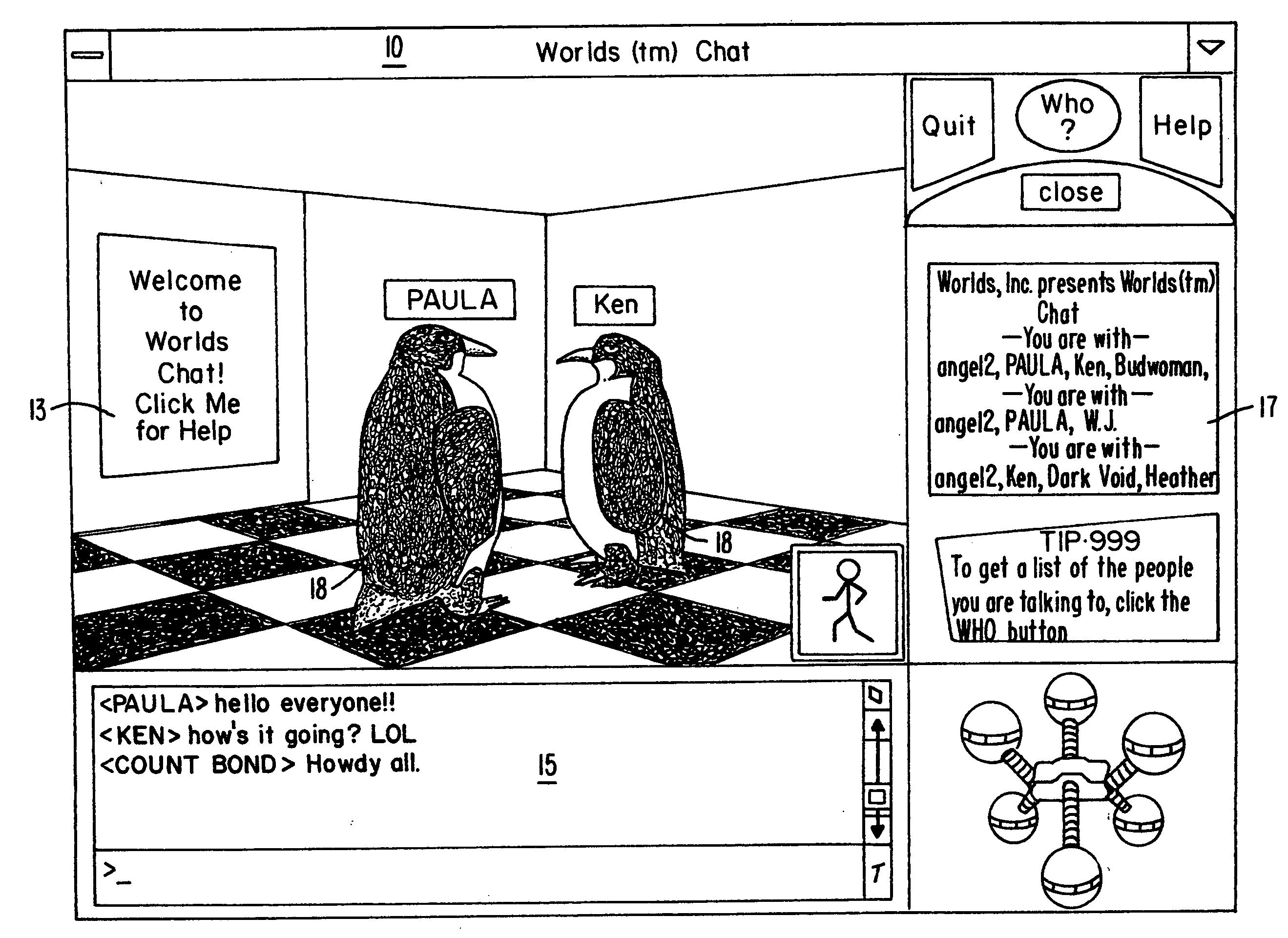
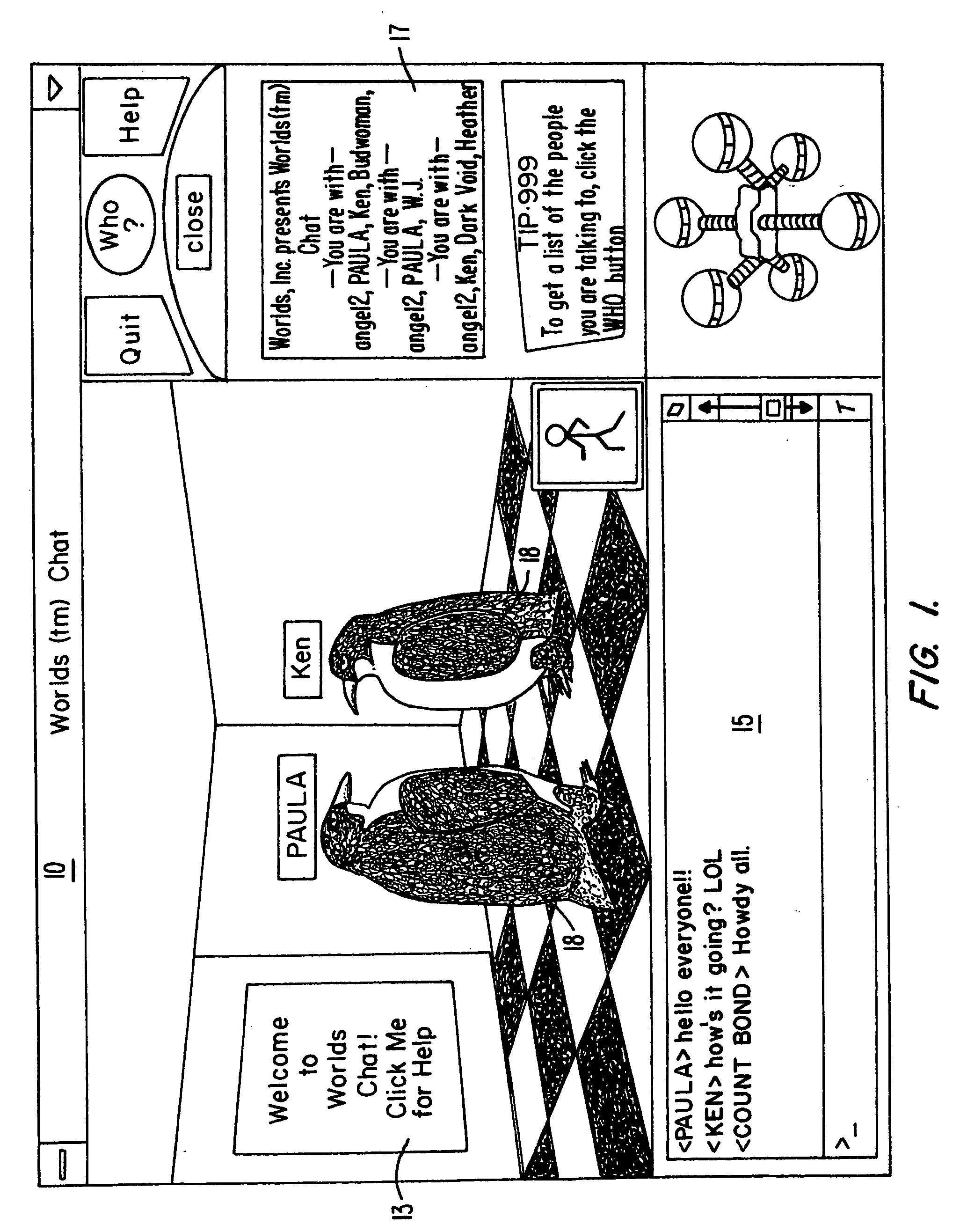
[0015] Although the preferred embodiment of the present invention can be used in a variety of applications, as will be apparent after reading the below description, the preferred embodiment is described herein using the example of a client-server architecture for use in a virtual world “chat” system. In this chat system, a user at each client system interacts with one or more other users at other client systems by inputting messages and sounds and by performing actions, where these messages and actions are seen and acted upon by other clients. FIG. 1 is an example of what such a client might display.

[0016] Each user interacts with a client system and the client system is networked to a virtual world server. The client system are desktop computers, terminals, dedicated game controllers, workstations, or similar devices which have graphical displays and user input devices. The term “client” generally refers to a client machine, system and / or process, but is also used to refer to the ...


PUM


Abstract

The present invention provides a highly scalable architecture for a three-dimensional graphical, multi-user, interactive virtual world system. In a preferred embodiment a plurality of users interact in the three-dimensional, computer-generated graphical space where each user executes a client process to view a virtual world from the perspective of that user. The virtual world shows avatars representing the other users who are neighbors of the user viewing the virtual word. In order that the view can be updated to reflect the motion of the remote user's avatars, motion information is transmitted to a central server process which provides positions updates to client processes for neighbors of the user at that client process. The client process also uses an environment database to determine which background objects to render as well as to limit the movement of the user's avatar.

Description

BACKGROUND OF THE INVENTION [0001] The present invention relates to the field of packet communications. More specifically, in one embodiment the invention provides an efficient communications network for client-server networks with large numbers of clients. [0002] A client-server network is a network where one or more servers are coupled to one or more clients over a communications channel. Typically, each server and each client is assigned an address so that each can determine which network messages are directed to it. While such a system may have only one server, it typically has many clients. A server object is one which waits for a request from a client object and then performs some service in response to the client request. A client is an object that makes the request. The designation of a particular object (computer hardware and / or software process) as a“server” object or a “client” object is not fixed. Thus, a given object can be a server for some services and a client of oth...

Claims


Application Information

Patent Timeline
Patent Type & Authority Applications(United States)
IPC IPC(8): G06F3/00H04W4/02A63F13/12H04L29/06H04L29/08H04W4/029
CPCA63F13/12G06F3/0482A63F2300/513A63F2300/5546A63F2300/5553A63F2300/572A63F2300/8082G06F3/04815G06N3/006H04L12/1813H04L12/1827H04L29/06H04L2029/06054H04W4/02H04W4/028H04L67/16H04L67/306H04L67/14H04L67/18H04L67/1002H04L67/10H04L67/38H04L69/329A63F2300/407H04W4/029H04L67/10015H04L67/1001H04L67/51H04L67/52H04L67/131A63F13/30A63F13/358G06F15/00G06F3/048H04L9/40H04L65/403
Inventor LEAHY, DAVECHALLINGER, JUDITHADLER, B. THOMASARDON, S. J.
Owner WORLDS
Learn More