Method for setting up a monitoring camera

a technology for applied in the field of monitoring cameras and monitoring systems, can solve problems such as image distortion in the client computer used, and achieve the effects of facilitating installation, less processing power, and facilitating installation

Active Publication Date: 2013-06-20
AXIS
View PDF3 Cites 7 Cited by
  • Summary
  • Abstract
  • Description
  • Claims
  • Application Information

AI Technical Summary

Benefits of technology

[0007]More specifically, according to one embodiment of the invention, a method for setting up a monitoring camera comprises tilting a camera head of the camera to a tilting position in which an optical axis of the camera substantially coincides with a rotational axis that the camera head is turning around when panning and in which the camera head is able to capture images through a wide angle lens arranged in a fixed position in relation to a base of the camera. The camera head is turned around the optical axis of the camera and capturing images by means of the camera head until wide angle images captured through the wide angle lens present the desired orientation. A home position value is stored for a pan motor of the camera, wherein the position value represents the position value for the pan motor when the captured wide angle image presents the desired orientation. The advantage of the above setup method is that the installation or set up relating to the camera becomes easier alternatively that the operation of the camera requires less processing power. Hence, the method is potentially facilitating installation and allows the use of either less powerful processors or other more process intensive applications to run on the monitoring camera.
[0008]According to one embodiment, the camera head captures overview images of a monitored area when capturing images through the wide angle lens. This is advantageous in that the camera may perform both overview surveillance and detailed identification in the same device, without investing in a plurality of cameras.

Problems solved by technology

Hence, the method is potentially facilitating installation and allows the use of either less powerful processors or other more process intensive applications to run on the monitoring camera.
However, if the lens used does not introduce as severe distortion, then the imagery may be distorted in a client computer used to display the imagery.

Method used


Image

  • Method for setting up a monitoring camera
  • Method for setting up a monitoring camera
  • Method for setting up a monitoring camera

Examples


Embodiment Construction

[0023]The present invention relates to a monitoring camera and facilitating setting up such a camera.

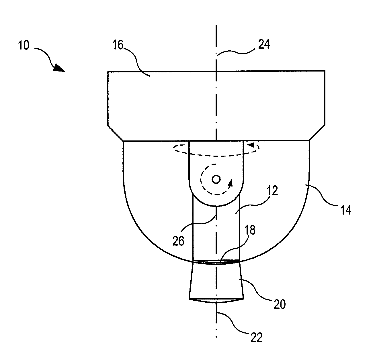
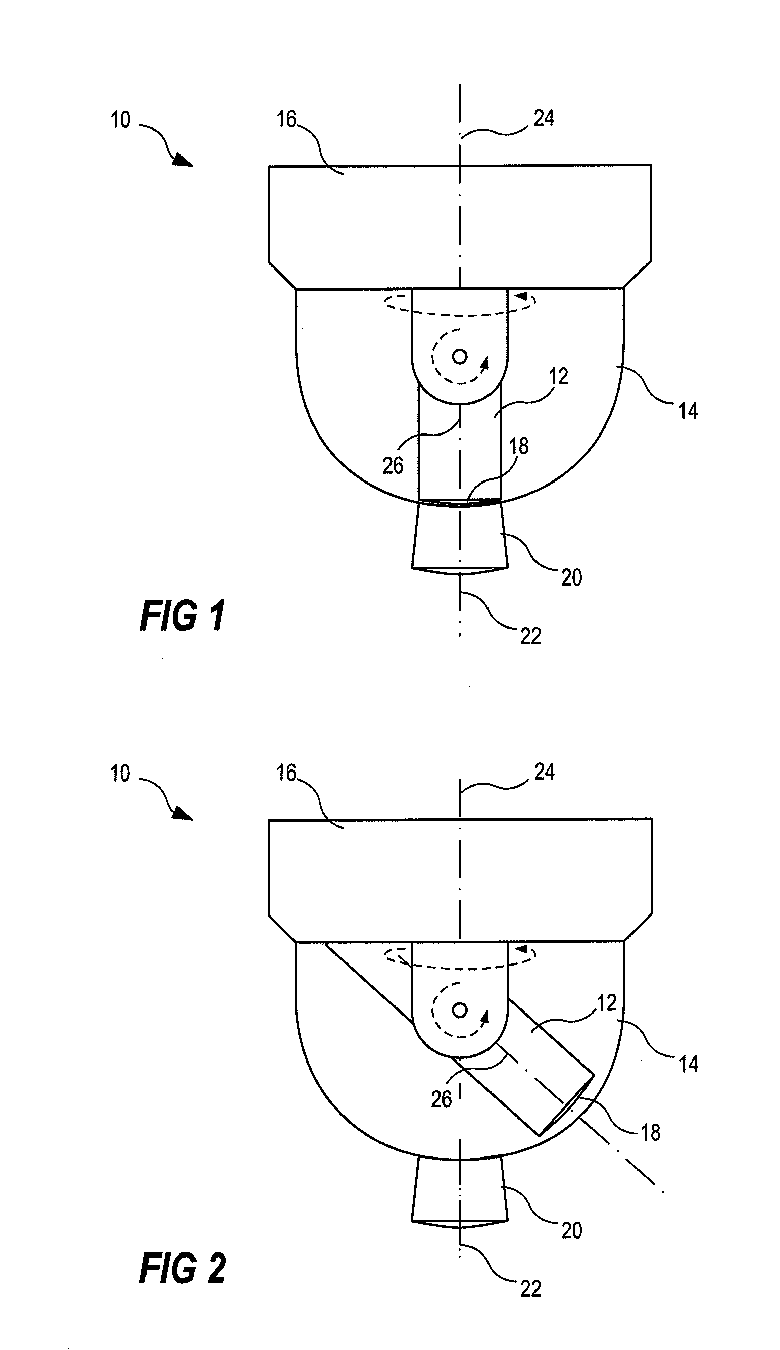
[0024]Referring to FIG. 1, according to one embodiment the monitoring camera 10 is a dome camera including a camera head 12, a transparent dome cover 14, and a dome base 16. The camera head 12 is enabled to pan and tilt by means of electronically controlled motors, not shown. The camera head 12 may be any known camera head that is enabled to pan and tilt. Further, the camera head 12 includes a lens 18. The lens 18 is arranged to focus light representing a scene to be captured by the camera 10 onto an image sensor in the camera head 12. The viewing angle of the captured image may be fixed or variable. Variable viewing angle may be accomplished by having a zoom enabled lens 18. In case of a fixed viewing angle lens the selection of the viewing angle may differ between different applications of the camera.

[0025]The dome camera further comprises a wide angle lens 20 mounted on the transp...


PUM


Abstract

A method for setting up a monitoring camera includes tilting a camera head of the camera to a tilting position in which an optical axis of the camera substantially coincides with a rotational axis that the camera head is turning around when panning, and in which the camera head is able to capture images through a wide angle lens arranged in a fixed position in relation to a base of the camera. The camera head is turned around the optical axis of the camera and captures images until wide angle images captured through the wide angle lens present the desired orientation. A home position value for a pan motor of the camera is stored, wherein the position value represents the position value for the pan motor when the captured wide angle image presents the desired orientation.

Description

TECHNICAL FIELD OF THE INVENTION[0001]The present invention relates to monitoring cameras and monitoring systems. In particular the present invention relates to a method for setting up a camera for use in a monitoring system.BACKGROUND OF THE INVENTION[0002]Monitoring systems typically include monitoring cameras. There are a great variety of types of monitoring cameras having somewhat different features and is used for slightly different purposes or situations. One of these types of monitoring cameras is the wide angle monitoring camera. The wide angle monitoring camera is used in situations where a large area is to be monitored and where details in the view is less important. If details are important, an additional camera generally is added to the monitoring installation. Most monitoring cameras are fixedly mounted at a predefined position and most of the time the camera is required to provide images of a particular camera view. In most cases, this requirement is fulfilled by manua...

Claims


Application Information

Patent Timeline
Patent Type & Authority Applications(United States)
IPC IPC(8): H04N7/18
CPCH04N5/232H04N7/18G03B17/12G03B5/00H04N23/63H04N23/695
Inventor BOKETOFT, CARL-OLAHANSSON, NIKLAS
Owner AXIS
Why Eureka
Try Eureka