Modelling of hand and arm position and orientation

a technology of applied in the field of primate hand and arm position and orientation modelling, can solve the problem of high complexity of finger movemen

Inactive Publication Date: 2013-06-20
DEUT PRIMATENZENT GMBH LEIBNIZ INST FUR PRIMATENFORSCHUNG
View PDF4 Cites 16 Cited by
  • Summary
  • Abstract
  • Description
  • Claims
  • Application Information

AI Technical Summary

Benefits of technology

[0011]According to the present invention, it is possible to model a position and orientation of a hand preferably without placing additional sensors to detect the positions and orientations of the metacarpal-phalangeal joint, the proximal interphalangeal joint, the distal interphalangeal joint of the finger.

Problems solved by technology

Finger movements are highly complex.
However, such a strip has to be provided under and above each joint.

Method used


Image

  • Modelling of hand and arm position and orientation
  • Modelling of hand and arm position and orientation
  • Modelling of hand and arm position and orientation

Examples


first embodiment

Configuration

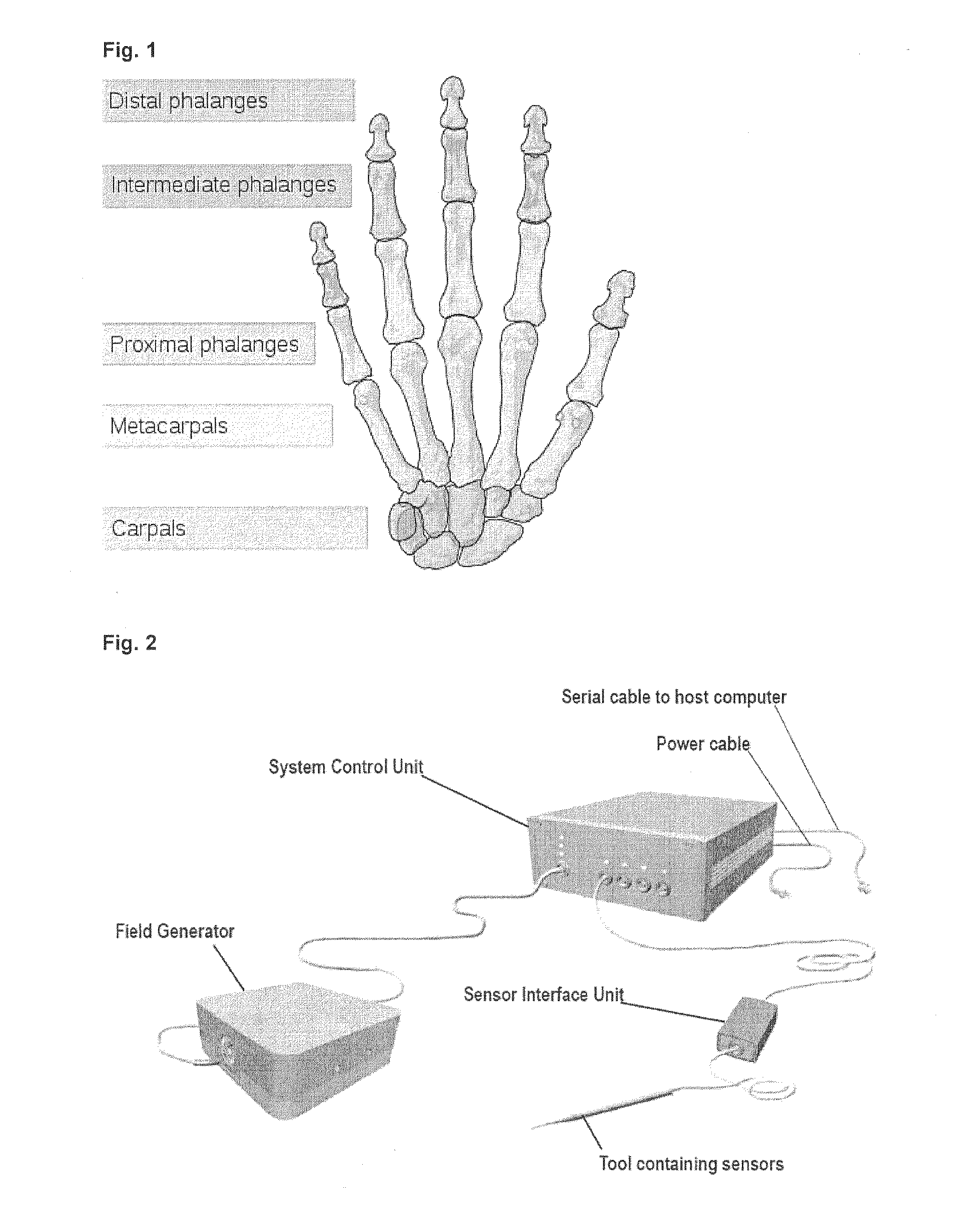
[0027]Referring to FIG. 2, the modelling system of the present embodiment includes a tool having a plurality of sensors to be attached to the finger and a separate modelling device, and uses an electro-magnetic principle to track hand and finger movements. In other words, the sensors to be placed on the fingers are sensor coils to which a varying magnetic field is applied and a resultant voltage is outputted to the modelling device.

[0028]As one example of such a modelling system a Aurora measurement system developed by Northern Digital Inc., Waterloo, Canada may be used. The measurement system may have a sampling rate of 40 Hz per sensor. A serial interface (Recommended Standard 232) may be used to transfer data from the system to a host computer with a maximum data rate of 115 kBaud.

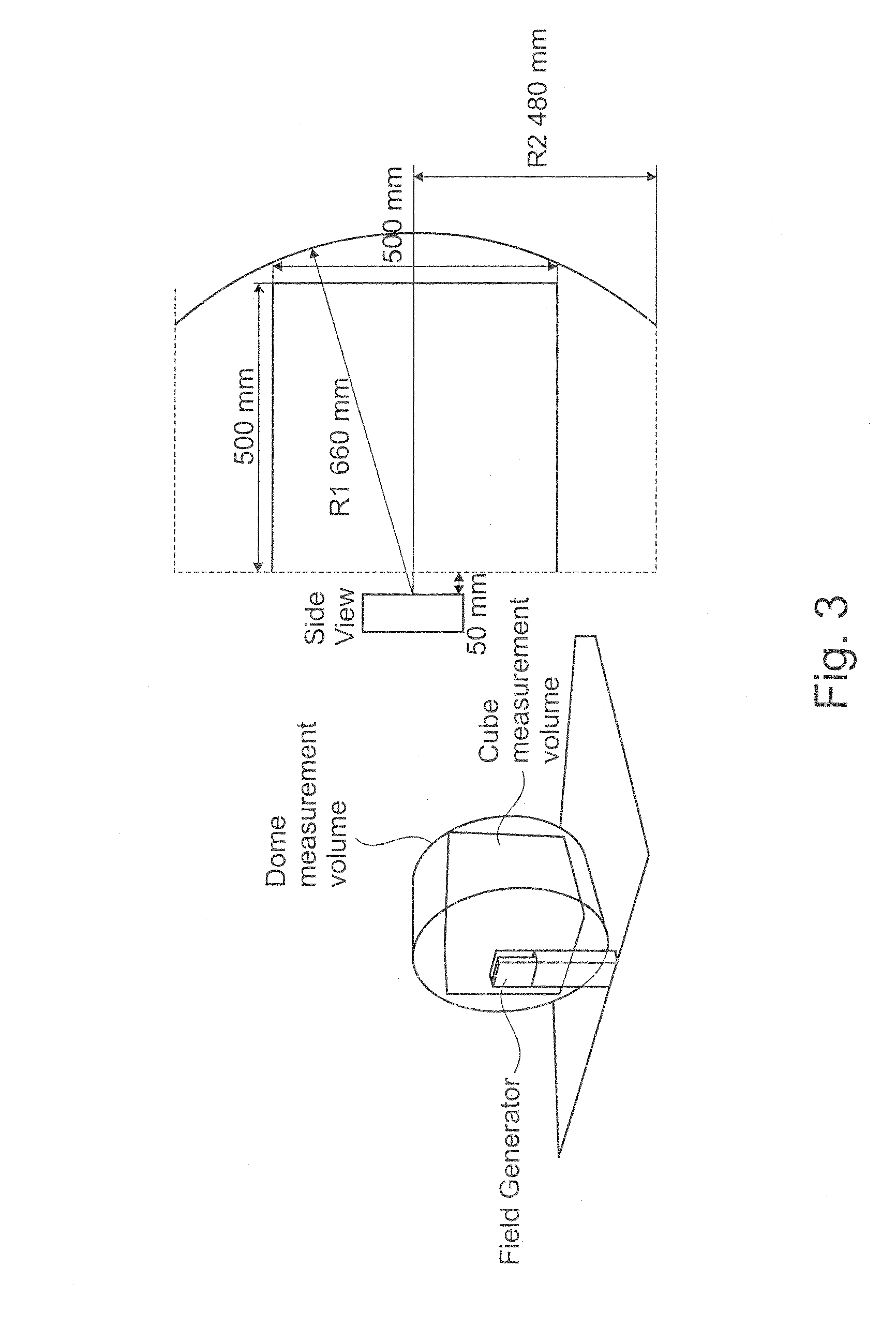
[0029]The modelling system includes a field generator, a system control unit (SCU), sensor coils and a host computer (not shown), and may further include a sensor interface unit (SIU). The ...

second embodiment

[0065]Next, a second embodiment of the present invention is explained. A modelling system according to the present embodiment includes a glove with sensors, instead of separate sensors to be attached to the hand.

[0066]Specifically, the glove has a first sensor on a portion of each glove finger corresponding to a phalanx distalis of a finger, and a second sensor at a position that is fixed on a portion (which may preferably be located at a non-visible place inside the glove) of the glove finger corresponding to a dorsum or palm of the hand. The first and second sensors are identical to those in the first embodiment. In one example, the first sensor is provided on a glove portion corresponding to the fingernail.

[0067]The hardware configuration is similar to that of the first embodiment shown in FIG. 2.

[0068]However, in the second embodiment, there is provided a storage (for example in the host computer) for storing a first distance between a point of the dorsum (the second sensor prov...

third embodiment

Arm-Modelling

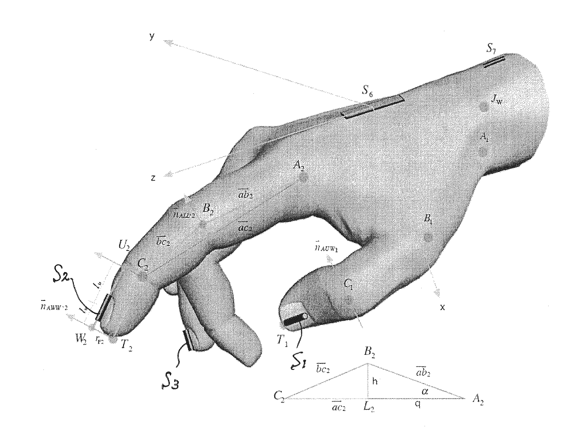
[0072]Referring to FIG. 11, a third embodiment of the present invention is explained. In the third embodiment, in addition to the hand-modelling an arm-modelling takes place. Namely, the positions and orientations of a shoulder joint Js, an elbow joint Je and a wrist joint Jw will be determined. These joints are assumed to be on the same plane. Also, the elbow joints Je and wrist joints Jw are preferably on a rotation axis of the forearm.

[0073]As explained below, an additional sensor (sensor coil) S7 to be placed on a forearm is needed to calculate positions and orientations of the entire arm. The axis of the sensor coil is placed along a longitudinal direction of the forearm.

[0074]A calculation method to be performed by the host computer (FIG. 2) will now be explained.

[0075]Assuming the shoulder position to be constant (e.g. the user sits on a chair), the position of the shoulder joint Js is determined. The length of the forearm is measured before the arm modelling.

[00...


PUM


Abstract

The present invention provides a method for modelling a position and orientation of a hand with as small a number of sensors as possible. A first sensor is attached on a phalanx distalis of a finger. The first sensor is adapted to provide information on at least five degrees of freedom that correspond to three translations, yaw and pitch. A second sensor is placed at a fixed position relative to a dorsum or palm of the hand. The second sensor is adapted to provide information on at least six degrees of freedom that correspond to three translations, yaw, pitch and roll with respect to a point of the dorsum or palm of the hand. A position and orientation of each of the first and second sensors is detected. A first distance between said point and a metacarpal-phalangeal joint of the finger, a second distance between the metacarpal-phalangeal joint and a proximal interphalangeal joint, a third distance between the proximal interphalangeal joint and a distal interphalangeal joint, and a fourth distance between the distal interphalangeal joint and the first sensor are measured. A position and orientation of each of the three joints is calculated on the basis of the measured first to fourth distances, the detected position and orientation of the first sensor, and the detected position and orientation of the second sensor.

Description

TECHNICAL FIELD[0001]The present invention relates to a method and system for modelling a position and orientation of a primate hand and arm.BACKGROUND OF THE ART[0002]Finger movements are highly complex. Therefore, humans spend much of their childhood learning to use their hands. Holding and moving objects of different size, shapes and weight is part of our early life, but the biomechanic system enabling these movements is highly sophisticated. The human hand as well as the hand or macaque monkeys are able to use 29 degrees of freedom. This fact and the wide range of motion (see Table below) allow primates to perform complex grasp types.TABLERange of motion of a human hand (C. Youngblut, R. E. Johnston,S. H. Nash et al., “Review of virtual environmentInterface technology,” I.f.D. Analyses, ed., 1996)(MCP: metacarpal-interphalangeal joint, PIP: proximal-interphalangeal joint, IP: interphalangeal-joint)JointMotionRangeThumbPalmar Adduction90°Radial Abduction80-90°Opposition90°MCP Fle...

Claims


Application Information

Patent Timeline
Patent Type & Authority Applications(United States)
IPC IPC(8): G01B7/00G06F17/00
CPCG06F3/014G06F17/00G01B7/00
Inventor SCHERBERGER, HANSJORGSCHAFFELHOFER, STEFAN
Owner DEUT PRIMATENZENT GMBH LEIBNIZ INST FUR PRIMATENFORSCHUNG
Why Eureka
Try Eureka