Cable Tray Mount

a cable tray and mount technology, applied in the direction of hose connection, workpiece holder, transportation and packaging, etc., can solve the problems of inability to adjust, limit the thickness of the mount, and the length of the fastener recess is set,

Active Publication Date: 2013-06-27
PANDUIT
View PDF20 Cites 40 Cited by
  • Summary
  • Abstract
  • Description
  • Claims
  • Application Information

AI Technical Summary

Benefits of technology

[0008]A cable tie mount for heavy equipment manufacturer applications is disclosed. The cable tie mount includes a body and at least one mount. The body has a base member and a receiving member that extends

Problems solved by technology

The existing fastener lengths and recess depths are set and cannot be adjusted.
The thickness of the mount is limited due to the set fastener lengths, and the width of the mount is limited due to the recessed area widths and other surrounding components.
The vinyl coating on the clamp wears and can expose the metal clamp or causes the grip to loosen on the secured item thereby potentially damaging the secured item.
However, manufacturers generally limit the ladder bracket to one or two lengths and try to specify which rung to attach to in an attempt to standardize components.
Installers frequently secure items to the wrong rung during assembly causing the harness routing length to not fit properly.
Also, attaching an item to the last rung is typically not allowed, but it does happen.
Fastening

Method used


Image

  • Cable Tray Mount
  • Cable Tray Mount
  • Cable Tray Mount

Examples


Embodiment Construction

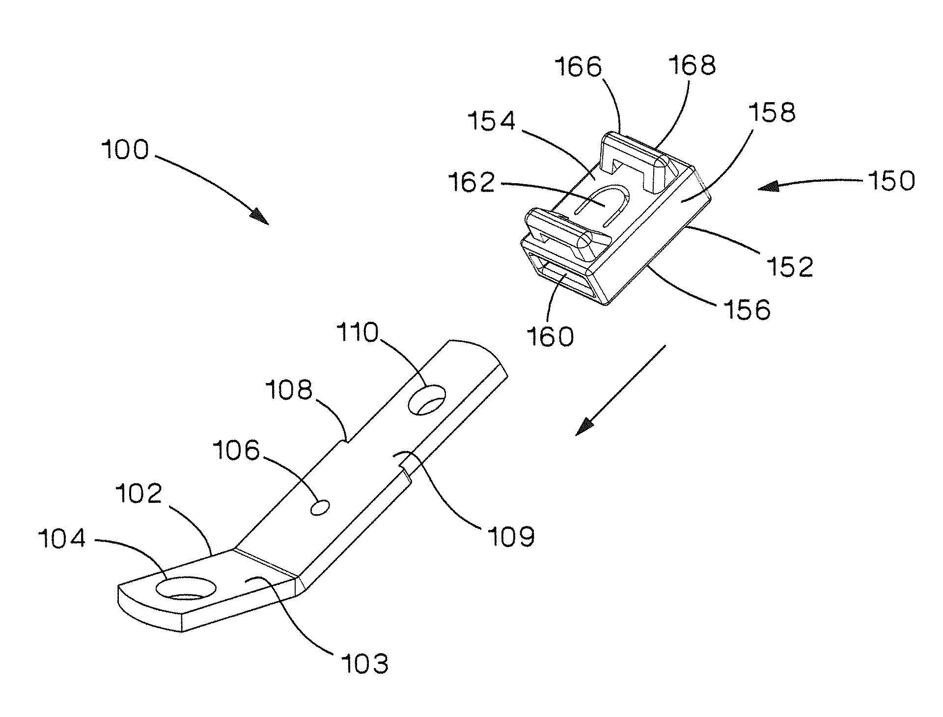
[0039]The present invention discloses heavy duty mounts for heavy equipment manufacturer applications. FIGS. 4-11 illustrate a two piece mount 100 that can be preassembled or field assembled without the use of tools. The two piece mount 100 includes a steel body 102 and a molded snap-on mount 150.

[0040]The steel body 102 is an angled body with a plurality of holes. The steel body 102 includes a base member 103 with a mounting hole 104 and a receiving member 109 with a locking hole 110. The locking hole 110 prevents the snap-on mount 150 from being pulled off of the body 102. The steel body 102 may include a grounding hole 106 for attaching a grounding cable from a wiring harness with a self-tapping screw. The steel body 102 also includes mount stops 108 to limit the insertion distance of the snap-on mount 150.

[0041]The steel body 102 allows high fastener torques which are required by heavy equipment manufacturers. The steel body 102 may be made with different lengths, with various a...


PUM


Abstract

The present invention is directed towards a cable tie mount. The cable tie mount includes a body and a mount. The mount includes a top, a bottom, sides, and a channel therethrough. The body has a base member with a mounting hole and a receiving member with a locking hole. The receiving member extends at an angle from the base member. The mount is installed on the receiving member of the body such that the receiving member is positioned within the channel of the mount.

Description

CROSS REFERENCE TO RELATED APPLICATION[0001]This application claims priority to U.S. Provisional Application No. 61 / 579,308, filed Dec. 22, 2011, the subject matter of which is hereby incorporated by reference in its entirety.FIELD OF THE INVENTION[0002]The present invention relates to a cable tie mount, and more particularly, to a cable tie mount for heavy equipment manufacturers.BACKGROUND OF THE INVENTION[0003]Heavy equipment manufacturers utilize several types of mounts to route cables, hoses, and tubing. Each mount includes a steel body that allows a high fastener torque and a vinyl, rubber, or plastic fastening surface to provide abrasion protection for the cable, hose, or tube being routed. Manufacturers have used vinyl coated or lined P clamps 50 (see FIG. 1), vinyl coated ladder brackets 60 (see FIG. 2), and nylon mounts insert molded with steel bushings 70 (see FIG. 3).[0004]The prior art mounts are fastened either to a threaded stud with a nut or to a threaded hole with a...

Claims


Application Information

Patent Timeline
IPC IPC(8): B65D63/00
CPCB65D63/00F16B5/0685Y10T24/1498Y10S269/903H02G3/32
Inventor HAJDUCH, MICHAEL P.
Owner PANDUIT
Why Eureka
Try Eureka