Gas lift pump apparatus with ultrasonic energy generator and method

a technology of ultrasonic energy generator and gas lift pump, which is applied in the direction of floating buildings, cleaning of hollow objects, insect catchers and killers, etc., can solve the problems of transporting zebra mussels between locations, and affecting the stability of the vessel

Active Publication Date: 2013-06-27
COLDHARBOR MARINE
View PDF10 Cites 4 Cited by
  • Summary
  • Abstract
  • Description
  • Claims
  • Application Information

AI Technical Summary

Benefits of technology

[0006]However, purging of a ballast tank requires emptying and refilling of the ballast tank. It will be understood that such a pr

Problems solved by technology

In an entirely separate technical field, the problem exists that aquatic nuisance species (ANS) such as Zebra mussels are being transported between locations such as between the US and Asia in the ballast tanks of maritime vessels.
However, pu

Method used


Image

  • Gas lift pump apparatus with ultrasonic energy generator and method
  • Gas lift pump apparatus with ultrasonic energy generator and method
  • Gas lift pump apparatus with ultrasonic energy generator and method

Examples


Embodiment Construction

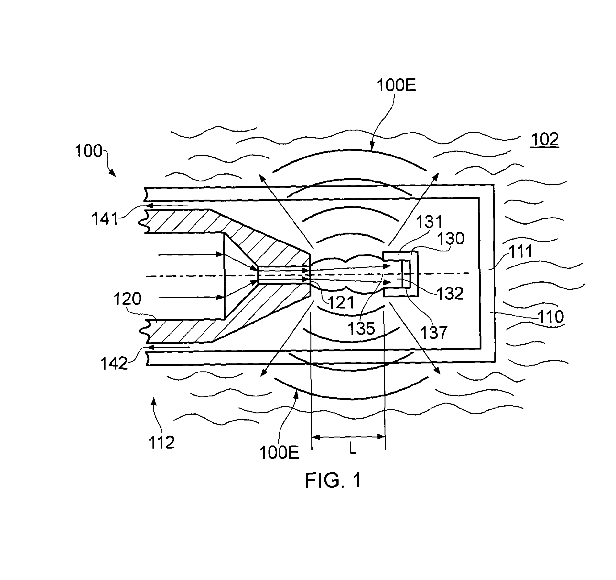
[0108]FIG. 1 shows a fluid delivery device 100 according to an embodiment of the invention. The device 100 has a resonance chamber 110 forming a body portion of the device 100 and a fluid nozzle 120 arranged to supply a flow of gaseous fluid into the resonance chamber 110 through an outlet aperture 121 of the nozzle 120. In some embodiments the device 100 is operated to provide a flow of gas (such as air, nitrogen or other gas such as another inert gas) out from the nozzle 120 at a supersonic velocity of around 300 ms−1 or greater. Other velocities are also useful.

[0109]In the embodiment shown the nozzle 120 is arranged to provide the flow of gaseous fluid into the resonance chamber 110 in a direction towards a first end 111 of the chamber 110 being a closed end.

[0110]At a second end 112 opposite the first end 111 the chamber 110 has openings 141, 142 arranged to allow gaseous fluid to flow out from the chamber 110.

[0111]In the embodiment of FIG. 1 a receptor member 130 is provided ...


PUM


Abstract

Gas lift pump apparatus comprising a column through which a liquid medium may be pumped by gas lift, the apparatus comprising a delivery device for delivering a flow of a gaseous fluid into the liquid medium, the device comprising means for generating ultrasonic energy therein by the flow of gaseous fluid therethrough, the device being operable to launch the ultrasonic energy into the liquid medium in the column.

Description

RELATED APPLICATIONS[0001]This application is a 35 U.S.C. §371 national stage application of PCT Application No. PCT / GB2011 / 051235, filed on 29 Jun. 2011, which claims priority from Great Britain Patent Application No. 1010907.2, filed 29 Jun. 2010, from Great Britain Patent Application No. 1014681.9, filed 4 Sep. 2010, and from Great Britain Patent Application No. 1017715.2, filed 20 Oct. 2010, the contents of which are incorporated herein by reference in their entireties. The above-referenced PCT International Application was published in the English language as International Publication No. WO 2012 / 001415 A9 on 5 Jan. 2012.FIELD OF THE INVENTION[0002]The present invention relates to an ultrasonic energy generation device and to a method of delivering ultrasonic energy. In particular but not exclusively the invention relates to an ultrasonic energy generation device for delivering a flow of fluid into a gas lift pump apparatus.BACKGROUND[0003]It is known to provide a gas lift pump...

Claims


Application Information

Patent Timeline
IPC IPC(8): B63J4/00A01M99/00F04F1/18
CPCB08B9/0326F04F1/18A01M99/00F04F7/00B63J4/002F04F1/20B08B9/043
Inventor WHITESIDE, RICHARD ERICREDGATE, DAVID BENJAMINWELLS, TOBIAS MARK
Owner COLDHARBOR MARINE
Why Eureka
Try Eureka