Dehumidifier

Active Publication Date: 2013-06-27
TAKUBO SEIKI SEISAKUSHO
View PDF17 Cites 6 Cited by
  • Summary
  • Abstract
  • Description
  • Claims
  • Application Information

AI Technical Summary

Benefits of technology

[0015]Further, according to the present invention, in the dehumidifier, a partition is disposed in the dehumidifying unit, and there are provided a humid air flow passage which the humid air passes through and a dry air flow passage which the dry air passes through. As a result, it is possible to efficiently perform dehumidifying process because the humid air before the dehumidifying process and the dry air after the dehumidifying processes are not mixed together.
[0016]Further, according to the present invention, in the dehumidifier, the heat exchanger comprises a casing arranged in a hollow box and a heat transfer unit accommodated in the casing, flat plates are turned back alternately in opposite directions, and a first flow passage and a second flow passage are prepared alternately in many layers between the flat plates, and among a front plate and a rear plate running in parallel to a return line of the flat plate of the casing, a high temperature fluid inlet and a high temperature fluid outlet being communicated with the second flow passage are disposed on the front plate side, and a low temperature fluid inlet and a low temperature fluid outlet being communicated with the first flow passage are disposed on the rear plate side, a lateral plate sealing member to cover entire region of the end unit and a pressing plate having rigidity are installed between lateral plate being at a position opposite to an end of the heat transfer unit and the heat transfer unit, a biasing means is disposed between the pressing plate and the lateral plate, the biasing means presses the lateral plate sealing member toward an end of the heat transfer unit via the pressing plate, and the lateral plate sealing member air-tightly blocks the first flow passage and the second flow passage. As a result, it is possible to carry out disassembling procedure in easier manner, and maintenance services such as cleaning can be conveniently performed.
[0017]Further, according to the present invention, in the dehumidifier, the biasing means is a coil spring arranged at a distribution rate as required, a flange nut is inserted from a side of the pressing plate of the coil spring, a spring supporting bolt to be inserted in the lateral plate is threaded on the flange nut, and by fastening the spring supporting bolt and by compressing t

Problems solved by technology

Thus, problems may arise that electric power consumption required for

Method used


Image

  • Dehumidifier
  • Dehumidifier
  • Dehumidifier

Examples


Example

[0029]Description will be given below on an embodiment of the present invention by referring to the attached drawings.

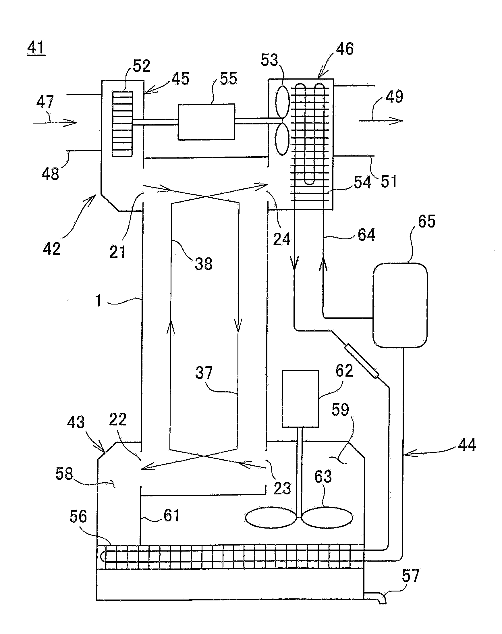
[0030]First, referring to FIG. 1, description will be given on an arrangement of a dehumidifier according to an embodiment of the present invention.

[0031]A dehumidifier 41 primarily comprises an air suction and discharging unit 42, a heat exchanger 1, a dehumidifying unit 43, and a refrigerant circulating system 44. The air suction and discharging unit 42 is disposed at an end of the heat exchanger 1, and the dehumidifying unit 43 is provided at the other end of the heat exchanger 1.

[0032]The air suction and discharge unit 42 comprises a suction unit 45 and a discharge unit 46. The suction unit 45 has a suction inlet 48 to suck humid air 47 and a high temperature fluid inlet 21 to take the humid air 47 into the heat exchanger 1. The discharge unit 46 has a low temperature fluid outlet 24 where dry air 49 flows in and a discharge outlet 51 to discharge the dry air 49....


PUM


Abstract

A dehumidifier comprises a suction unit 45 which humid air 47 is sucked in, a dehumidifying unit 43 having a chiller 56 and for cooling down the humid air sucked in and for dehumidifying by condensing the moisture in the humid air, a discharge unit 46 having a heat radiator 54 and for heating and discharging dry air 49 as dehumidified at the dehumidifying unit, a refrigerant circulating system 44 for cooling down the humid air at the dehumidifying unit and for heating the dry air at the discharge unit, and a heat exchanger 1 for performing heat exchange between the humid air and the dry air as dehumidified at the dehumidifying unit.

Description

BACKGROUND OF THE INVENTION[0001]The present invention relates to a dehumidifier to be installed in a room such as a drying chamber and is used to dehumidify the air in the room.[0002]A type of dehumidifier has been known in the past, according to which a chiller is cooled down by vaporization heat, i.e. by vaporizing a refrigerant in liquid state. Then, humid air sucked from outside is chilled down by a chiller, and the humid air is dehumidified by condensation of the moisture contained in the humid air by chilling. The refrigerant is then liquefied by compressor, and dry air thus dehumidified is heated by condensation heat generated at the time of liquefaction. Then, the dry air is discharged to outside.[0003]However, in case of a conventional type dehumidifier, temperature difference between the temperature of the humid air sucked from outside and the temperature of the dry air, which has been chilled down and dehumidified, is risen. Thus, problems may arise that electric power c...

Claims


Application Information

Patent Timeline
IPC IPC(8): F25B29/00
CPCF25B29/00D06F58/206B01D53/265F24F13/30F24F3/153F24F12/006F28D9/0025F24F2003/1446F24F2003/1452F28D2021/0038F28F2230/00B01D2259/4508Y02B30/563D06F58/24F28F2275/20F24F3/1405Y02B30/56
Inventor TAKUBO, SADAO
Owner TAKUBO SEIKI SEISAKUSHO
Why Eureka
Try Eureka