Charging unit and electrical device provided with the same

a charging unit and electrical device technology, applied in the direction of emergency power supply arrangement, safety/protection circuit, transportation and packaging, etc., can solve the problems of unnecessari consumption of battery power and consumed power stored in the battery, and achieve the effect of preventing the consumption of battery power

Inactive Publication Date: 2013-06-27
HITACHT MAXELL LTD
View PDF6 Cites 9 Cited by
  • Summary
  • Abstract
  • Description
  • Claims
  • Application Information

AI Technical Summary

Benefits of technology

[0018]According to the charging unit of the embodiment of the present invention, a disconnecting section that disconnects a battery and a charge controller when the battery is not being charged, is provided between the charge controller and the battery. As a result, power in the battery can be prevented from being unnecessarily consumed due to current flow into the charge controller when the battery is not being charged.

Problems solved by technology

Incidentally, in the above-described configuration in which the charge circuit is provided in the device including the battery, power stored in the battery is consumed due to a leakage current of the charge circuit and the like.
As a result, when the battery is not being charged, power of the battery is unnecessarily consumed even when the device is not being used.

Method used


Image

  • Charging unit and electrical device provided with the same
  • Charging unit and electrical device provided with the same
  • Charging unit and electrical device provided with the same

Examples


first embodiment

Advantages of First Embodiment

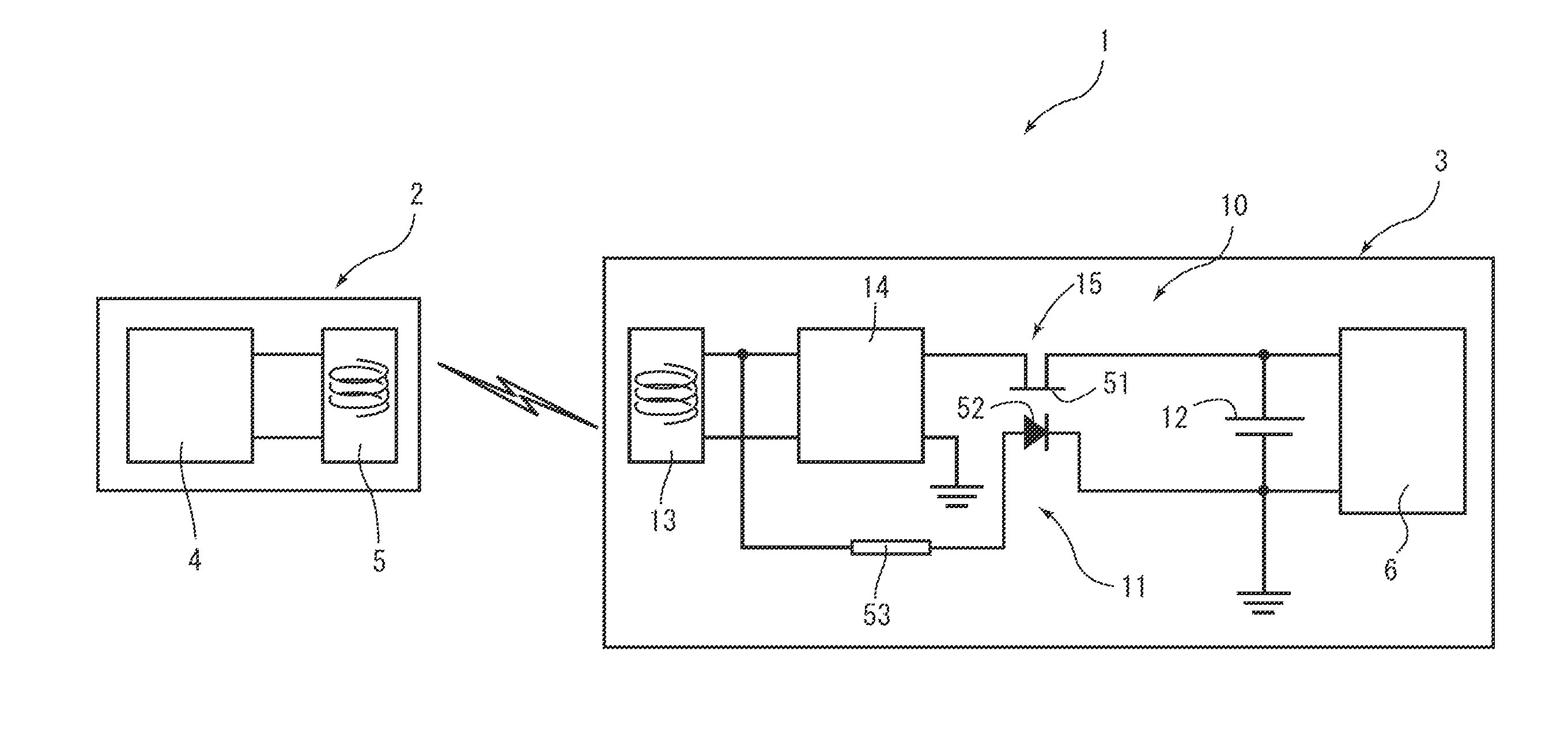
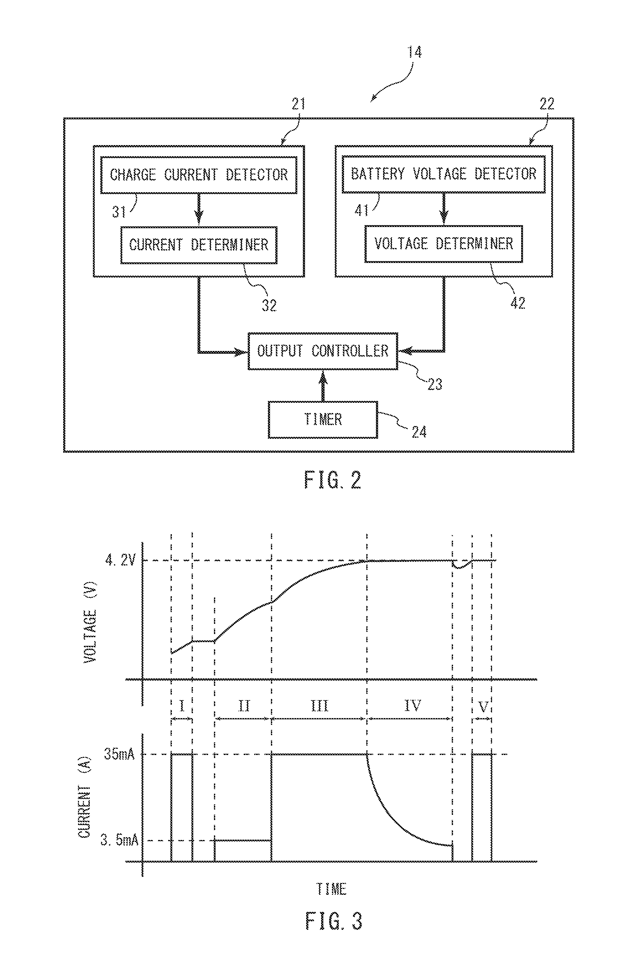
[0063]Thus, in this embodiment, the relay 15 that electrically disconnects the charge controller 14 and the battery 12 when the battery 12 is not being charged, is provided between the charge controller 14 that controls charging of the battery 12, and the battery 12. As a result, power in the battery 12 can be prevented from being unnecessarily consumed due to the leakage current of the charge controller 14 when the battery 12 is not being charged.

[0064]Also, in this embodiment, the relay 15 includes the switch 51 that is put into the conducting or non-conducting state, depending on light, and the light emitter 52 that emits light when a current flows through the power receiving coil 13. As a result, when the battery 12 is not being charged, i.e., a current is not flowing through the power receiving coil 13, the light emitter 52 does not emit light, and therefore, the switch 51 can electrically disconnect the charge controller 14 and the battery 12. The...

second embodiment

Advantages of Second Embodiment

[0073]Thus, in this embodiment, the transistor 61 that is put into the conducting state when the voltage of the output side of the power receiving coil 13 is higher than or equal to the threshold, and is put into the non-conducting state when the voltage of the output side of the power receiving coil 13 is lower than the threshold, is provided between the charge controller 14 and the battery 12. As a result, when the battery 12 is charged, i.e., the power feeding coil 5 of the charger 2 causes the voltage of the output side of the power receiving coil 13 to be higher than or equal to the threshold, the transistor 61 can be put into the conducting state, so that the battery 12 can be charged. On the other hand, when the battery 12 is not charged, i.e., the voltage of the output side of the power receiving coil 13 is lower than the threshold, the transistor 61 can be put into the non-conducting state. Therefore, in the configuration of this embodiment, a...

third embodiment

Advantages of Third Embodiment

[0079]Thus, according to this embodiment, the diode 71 that allows only current flow from the charge controller 14 to the battery 12 is provided between the charge controller 14 and the battery 12. As a result, the diode 71 can block current flow from the battery 12 to the charge controller 14. Therefore, power in the battery 12 can be prevented from being unnecessarily consumed due to the leakage current of the charge controller 14.

[0080]In addition, in the configuration of this embodiment, it is not necessary to drive or control a switch or the like. Therefore, a circuit having a simple configuration can be used to achieve the above advantages.

[0081]Moreover, with the above configuration, power of the battery 12 consumed by the charge controller 14 can be reduced irrespective of the conduction state of the power receiving coil 13 of the charging unit 70. In other words, even if the device is not placed far away from the charger 2, current flow from th...


PUM


Abstract

In a charging unit, a configuration is obtained in which power stored in a battery can be prevented from being unnecessarily consumed when a device is not being used. The charging unit (10) includes a power receiver (13) (power receiving coil) that receives power from a power feeder (2) (charger), a battery (12) that is charged with power received by the power receiver (13), a charge controller (14) that is provided between the power receiver (13) and the battery (12), and controls the battery (12), and a disconnecting section (15) (relay) that is provided between the battery (12) and the charge controller (14), and electrically disconnects the battery (12) and the charge controller (14) when the battery (12) is not being charged.

Description

TECHNICAL FIELD[0001]The present invention relates to charging units including a battery and a charge controller that controls charging of the battery, and electrical devices including the charging unit.BACKGROUND ART[0002]A charging unit including a battery and a charge controller that controls charging of the battery is conventionally known. As such a charging unit, for example, as disclosed in JP 2010-34080 A, a configuration is known in which a charge circuit (charge controller) for controlling charging of the battery is provided in a device in which the battery is mounted.[0003]Note that the above JP 2010-34080 A discloses a non-contact charging system that has a coil in each of a charger and a device. In the non-contact charging system, a magnetic field generated when a current is caused to flow through the coil in the charger is used to cause a current to flow through the coil in the device. In other words, so-called electromagnetic induction is used to charge the battery.DIS...

Claims


Application Information

Patent Timeline
Patent Type & Authority Applications(United States)
IPC IPC(8): H02J7/02H02J7/00H02J7/34
CPCH02J7/025H02J7/0031H02J9/002H02J7/0073H02J5/005H02J7/0071H02J50/70H02J50/10H02J50/12
Inventor TAKEUCHI, KYOHEIHASHIMOTO, MASATOSHITANII, KEIICHI
Owner HITACHT MAXELL LTD
Why Eureka
Try Eureka