Combine power selection system

Inactive Publication Date: 2005-03-15
BLUE LEAF I P +1
View PDF16 Cites 52 Cited by
  • Summary
  • Abstract
  • Description
  • Claims
  • Application Information

AI Technical Summary

Benefits of technology

An object of the present invention is to provide an engine speed control system for a combine harvester, the control system avoiding power overload of

Problems solved by technology

This limits the maximum grou

Method used


Image

  • Combine power selection system
  • Combine power selection system
  • Combine power selection system

Examples


Embodiment Construction

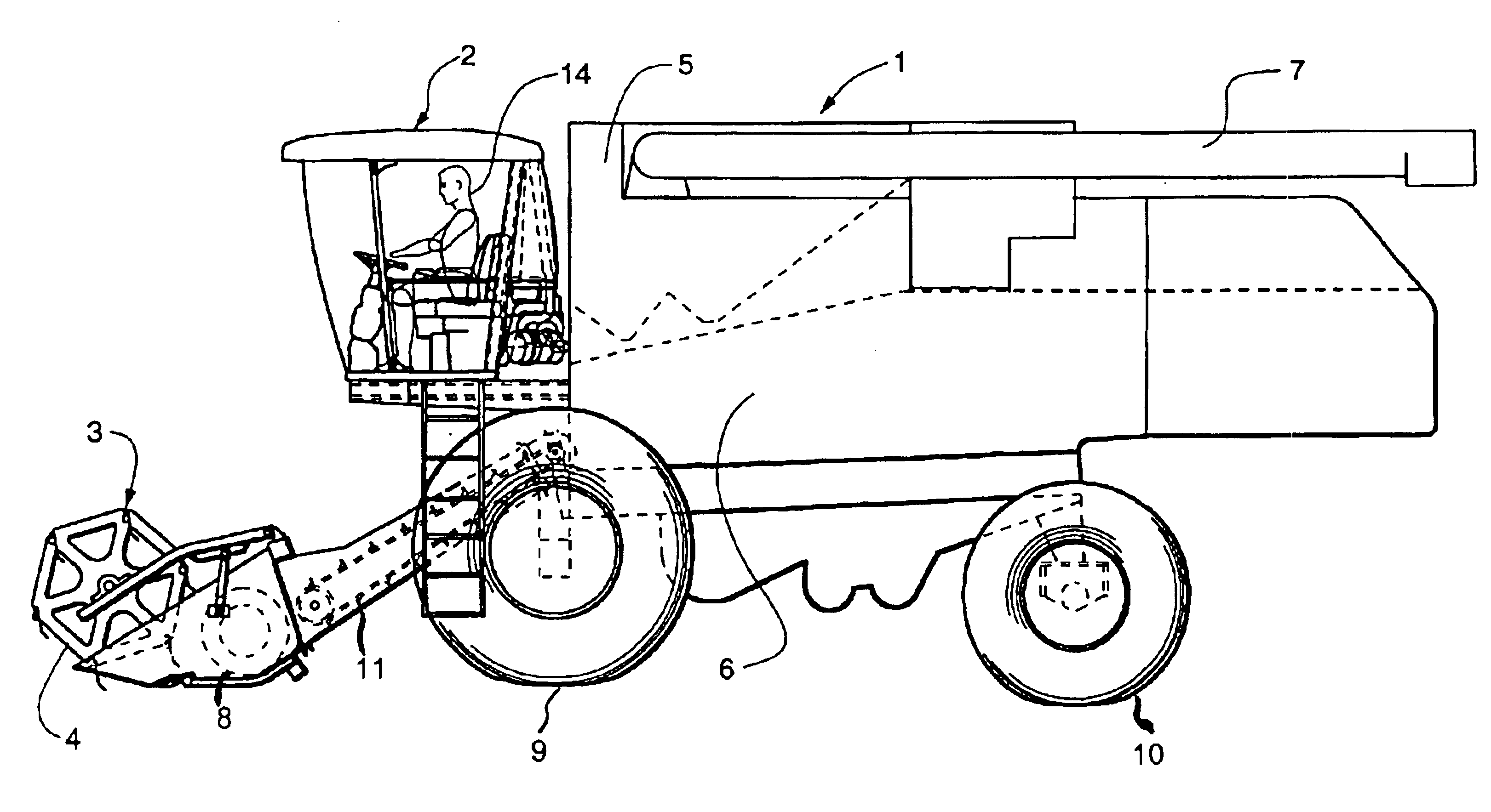
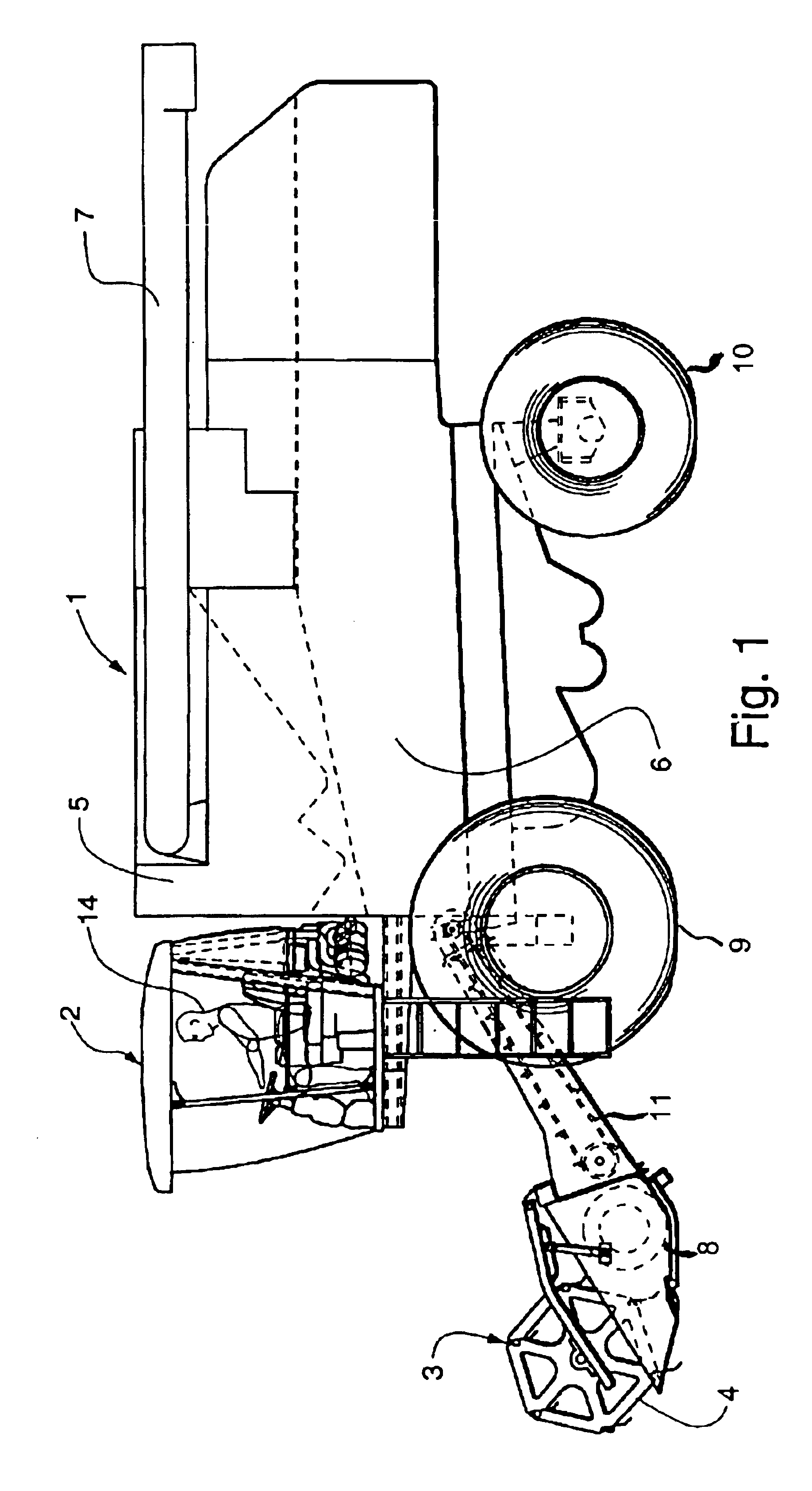
FIG. 1 illustrates a typical twin rotor combine in which the present invention may be used. The combine 1 includes a header 3 having a reel 4 for cutting crop as the combine moves forwardly over a crop field. Crop material (grain and stalks) cut by reel 4 is fed to a transverse rotating auger 8 that moves the crop material toward the center of the header. From auger 8, the crop material is picked up by a conveyor 11 and fed to a threshing, separation and cleaning system 6 that separates the stalk material and chaff from the grain. The processed grain is stored in a grain tank 5 positioned near the top of the combine and the stalk material is discharged from the rear of the combine. The grain is removed from the grain tank by an unloading auger (not shown) through a grain tank unload tube 7. The unload tube 7 is pivotally mounted so that it may swing outwardly, thus permitting the discharge of processed grain into a truck or cart (not shown) moving along side the combine.

Referring to...


PUM


Abstract

A system for propelling a combine over the ground and driving other components of the combine includes an engine driving a transmission via a hydrostatic drive system. A microprocessor stores a work table and a road table for controlling engine speed. A gear selector operates a switch to select one of the tables and a throttle control operates switches to select a speed value from the selected table. When working a field, the work table is selected so that the engine runs at speeds in a range suitable for driving the other components. For transport of the combine the road table is selected so that the engine may run at a speed higher than speeds suitable for driving the other components. For a given setting of the throttle control, the engine is controlled to run at either a first or second speed depending on the setting of the gear select lever.

Description

FIELD OF THE INVENTIONThe present invention relates to an engine speed control system for a combine harvester having a hydrostatic wheel drive system for propelling the combine over the ground. More particularly, the invention provides for alternate engine speeds for a single setting of a throttle control member.BACKGROUND OF THE INVENTIONSome combines employ a hydrostatic drive system wherein an internal combustion engine drives a hydrostatic pump. The pump drives a hydrostatic motor, the motor in turn driving the wheels of the combine through a transmission to propel the combine over the ground. Hydraulic flow from the pump to the hydrostatic motor is governed by the displacement of the hydrostatic pump and the speed at which the pump is driven by the engine. Typically, the engine also provides power to operate other components of the combine such as the header, threshing unit and unload tube conveyor and positioning unit. The power for driving these components is obtained by a po...

Claims


Application Information

Patent Timeline
IPC IPC(8): A01D41/00A01D41/127
CPCA01D41/1274B60W10/06Y10T477/68B60K2031/0091Y02P60/14B60W50/082B60W50/085
Inventor HEISEY, RICHARD D.
Owner BLUE LEAF I P
Why Eureka
Try Eureka