Downchirped pulse amplification

a pulse compressor and downchirped technology, applied in the direction of pulse automatic control, electromagnetic transmission, transmission, etc., can solve the problems of easy acquisition, easy alignment of pulse compressors, and virtually lossless transparent materials, so as to avoid thermal distortion effects, accurate dispersion compensation, and avoid average power typical of grating pulse compressors

Inactive Publication Date: 2006-07-04
UNIV OF COLORADO THE REGENTS OF
View PDF14 Cites 52 Cited by
  • Summary
  • Abstract
  • Description
  • Claims
  • Application Information

AI Technical Summary

Benefits of technology

[0014]Although similar elements, such as grating pairs, are used in some embodiments of the present invention as were employed in the prior art, there is an important difference. The grating pairs are used before amplification, so that the loss induced can be made up for with just a slightly higher gain in the amplifier.
[0016]However, the use of a simple transparent optical element has a number of very significant advantages over past pulse compressor designs. First, a transparent material can be virtually lossless. Thus, the 30–50% loss in average power typical of a grating pulse compressor can be avoided. Furthermore, thermal distortion effects are also avoided. Second, a simple block of glass is alignment insensitive, making alignment of the pulse compressor, and accurate dispersion compensation, much simpler to obtain.

Problems solved by technology

First, a transparent material can be virtually lossless.
Second, a simple block of glass is alignment insensitive, making alignment of the pulse compressor, and accurate dispersion compensation, much simpler to obtain.

Method used


Image

  • Downchirped pulse amplification
  • Downchirped pulse amplification
  • Downchirped pulse amplification

Examples


Embodiment Construction

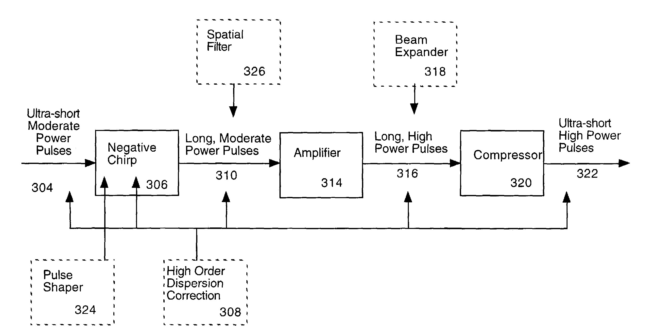
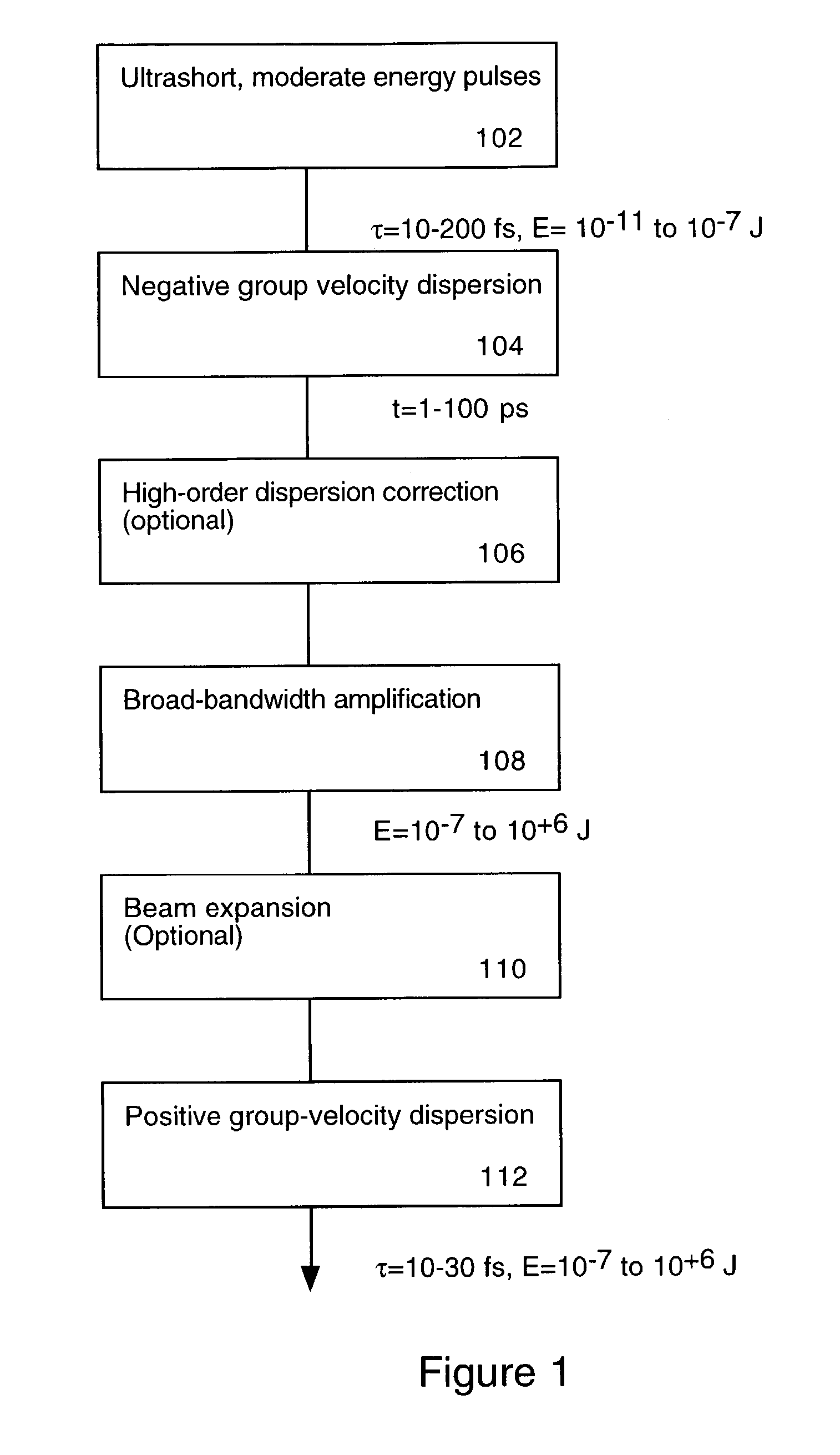
[0024]FIG. 1 is a flow diagram illustrating the downchirped pulse amplification (DPA) technique of the present invention. In step 102, the initial, low energy, ultrashort pulse is generated. A typical length of such a pulse is 10–20 femtoseconds, and a typical energy is 10−11 to 10−7 Joules. In step 104 the pulse is stretched using negative group velocity dispersion, resulting in a much longer, negatively chirped pulse. The length of the pulse might be on the order of 1 to 100 picoseconds. In step 106, high-order dispersion correction is applied. This step is not required, but is desirable. In practice, steps 104 and 106 are performed simultaneously using a combination of optical elements in an order that can often be interchanged.

[0025]In step 108 broad-band amplification is applied to the stretched pulse. The energy of the pulse would be on the order of 10−7 to 10+6 Joules after amplification. Step 110 accomplishes beam expansion, if desired. Beam expansion is useful for preventin...


PUM


Abstract

An ultrashort pulse amplifier produces high-power ultrafast laser pulses. Pulses first have net negative (i.e. blue to red) chirp applied, and are then amplified in a laser amplifier. After amplification, the pulses are compressed using propagation through a block of material or other convenient optical system with a positive sign of chromatic dispersion. High-order dispersion correction may also be included.

Description

BACKGROUND OF THE INVENTION[0001]This application claims the benefit of U.S. Provisional Application No. 60 / 379,903 filed May 10, 2002.FIELD OF THE INVENTION[0002]The present invention relates to techniques for amplifying ultrashort pulses.PROBLEMS IN THE ART[0003]The technique of Chirped-Pulse Amplification (CPA) is well established as a method for generating high peak-power pulses with duration of approximately 10 femtoseconds to 10 picoseconds. In CPA, ultrashort light pulses originating from a mode-locked laser are “chirped” by passing them through either a dispersive pulse stretcher, by propagating the light through an optical fiber, or through some other means of introducing a positive (sometimes called “normal”) chromatic dispersion. Positive, or normal, chirping results in a pulse whose instantaneous frequency increases in frequency from beginning to end.[0004]The effect of the “chirp” is to increase the time-duration of the light pulse. An ultrashort light pulse necessarily...

Claims


Application Information

Patent Timeline
Patent Type & Authority Patents(United States)
IPC IPC(8): H01S3/00H01S3/05H01S3/23
CPCH01S3/0057H01S3/2308
Inventor KAPTEYN, HENRY C.BACKUS, STERLING J.
Owner UNIV OF COLORADO THE REGENTS OF
Why Eureka
Try Eureka