
Camera module and method for driving the same

a technology of camera module and camera module, which is applied in the direction of color television details, television system details, television systems, etc., can solve the problems of inconvenient brightness adjustment by users, and achieve the effects of increasing or decreasing the brightness of a particular area, reducing the difficulty of users adjusting brightness, and improving the brightness of the area

Active Publication Date: 2013-06-27
LG INNOTEK CO LTD
View PDF5 Cites 11 Cited by
  • Summary
  • Abstract
  • Description
  • Claims
  • Application Information

AI Technical Summary

Benefits of technology

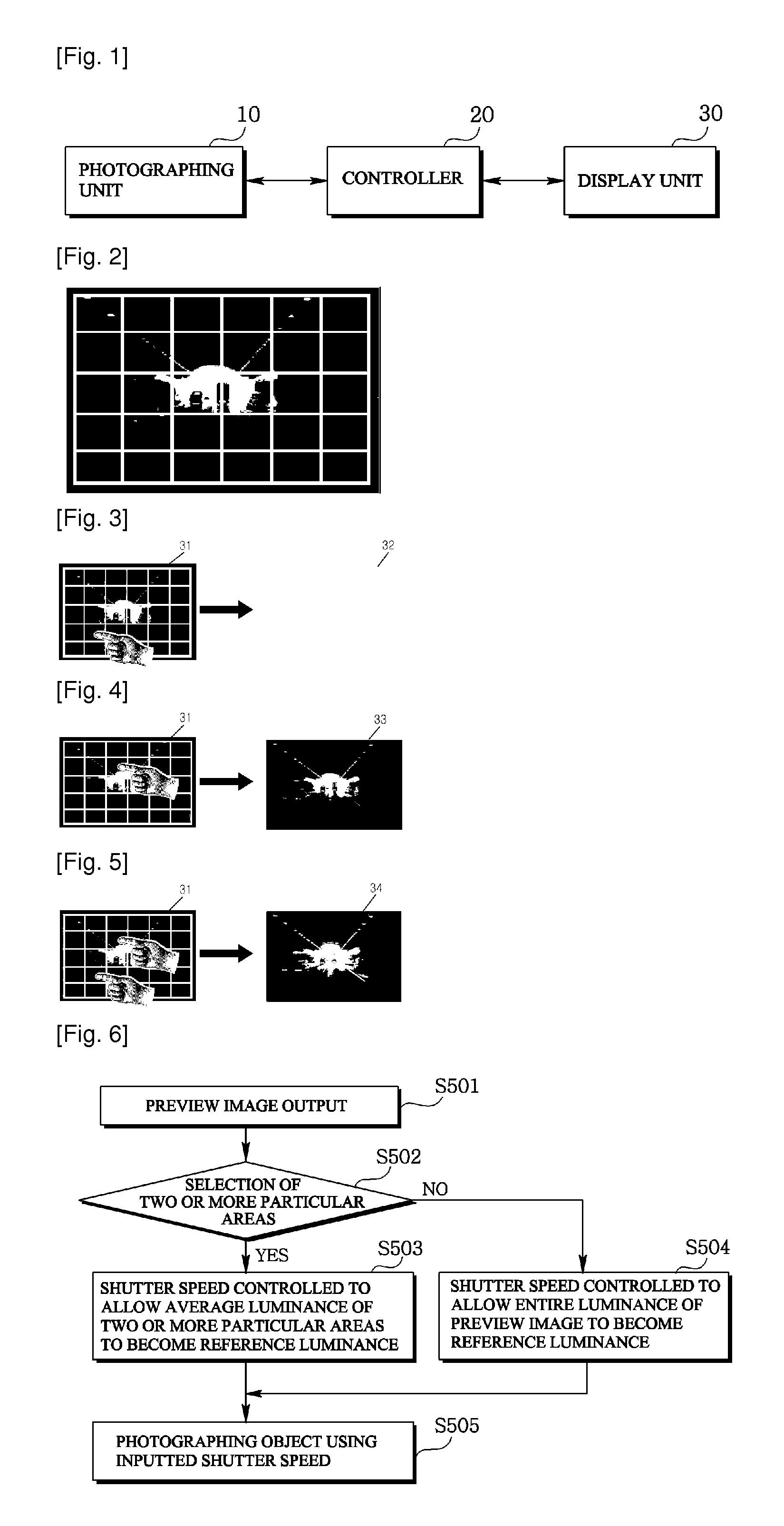
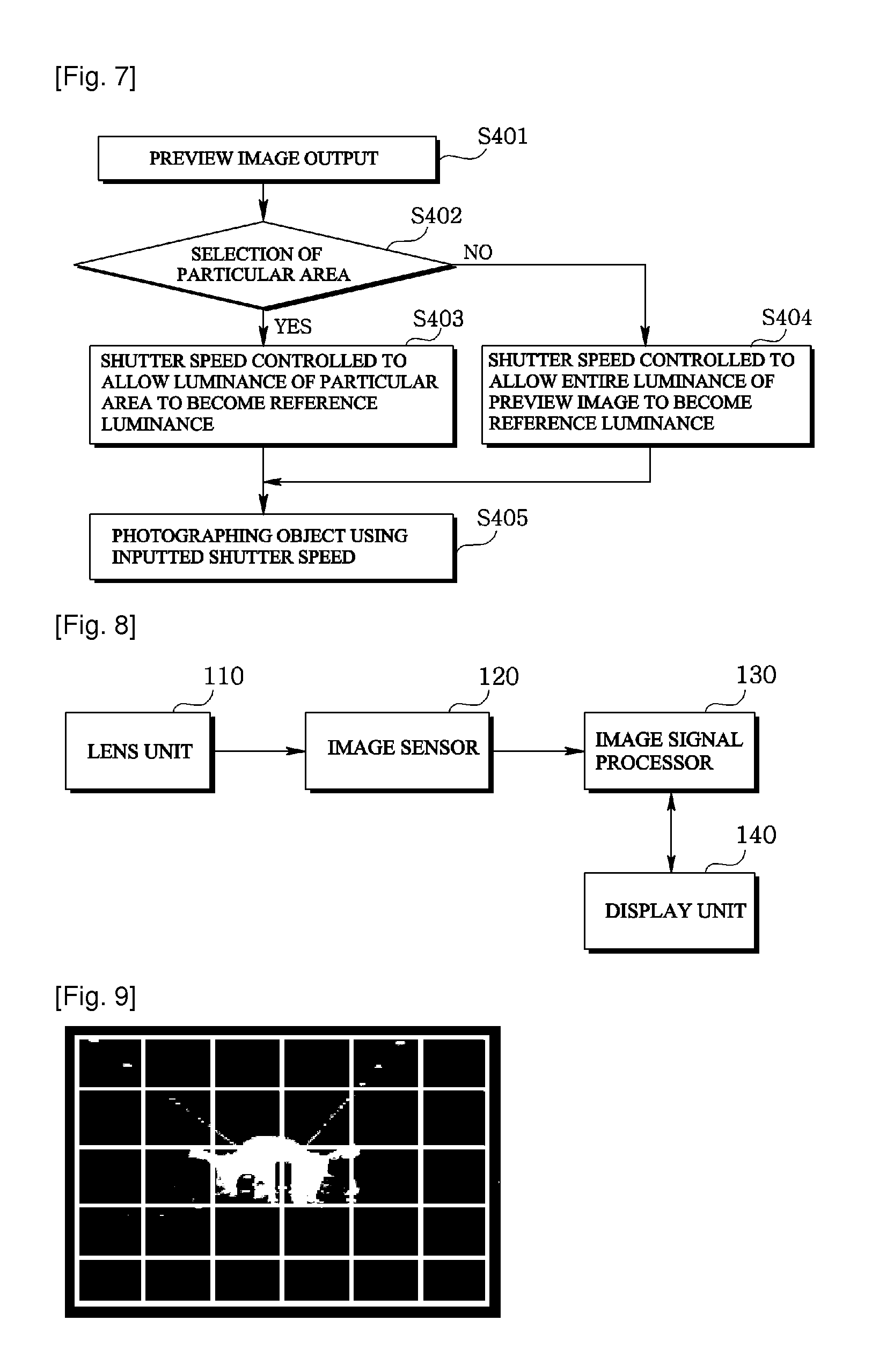
The present invention relates to a camera module and a method for driving it. The technical effects of the invention include adjusting shutter speed to equal brightness of selected areas in a preview image, allowing for photographing of varying brightness levels. Additionally, the invention allows for adjusting brightness of a selected area based on user preferences, visually checking and adjusting the image through a display unit, and setting focus based on a user's finger area. Furthermore, the invention allows for adjusting the distance between two finger areas to adjust the size of the desired focal area.

Problems solved by technology

Generally, an AE method is configured to adjust brightness of an output image based on brightness of entire image photographed by the camera module, such that there is inconvenience of adjusting the brightness by a user in order to obtain a desired level of brightness in a particular area.

Method used


Image

  • Camera module and method for driving the same
  • Camera module and method for driving the same
  • Camera module and method for driving the same

Examples


Embodiment Construction

[0057]The following description is not intended to limit the invention to the form disclosed herein. Consequently, variations and modifications commensurate with the following teachings, and skill and knowledge of the relevant art are within the scope of the present invention. The embodiments described herein are further intended to explain modes known of practicing the invention and to enable others skilled in the art to utilize the invention in such, or other embodiments and with various modifications required by the particular application(s) or use(s) of the present invention.

[0058]The disclosed embodiments and advantages thereof are best understood by referring to FIGS. 1-17 of the drawings, like numerals being used for like and corresponding parts of the various drawings. Other features and advantages of the disclosed embodiments will be or will become apparent to one of ordinary skill in the art upon examination of the following figures and detailed description. It is intended...


PUM


Abstract

The present invention relates to a camera module and a method for driving the camera module, the module including: a photographing unit controlling a shutter speed to photograph an image in response to an inputted control signal; a display unit displaying the image; and a controller outputting a first shutter speed control signal to the photographing unit to allow an average brightness of two or more particular areas to become a set reference brightness, in a case the two or more particular areas in a plurality of divided areas in the display unit are selected.

Description

TECHNICAL FIELD[0001]The teachings in accordance with the exemplary embodiments of this invention relate generally to a camera module and a method for driving the camera module.BACKGROUND ART[0002]A camera module mounted in small-sized terminals such as digital cameras or portable phones employs an image sensor or a photoelectric conversion device such as a charge coupled apparatus (CCD) type or a complementary metal oxide semiconductor (CMOS) type to converge light from objects to a photosensitive element and to form images of the objects. The camera module is embedded with an auto exposure (AE) function to adjust brightness level of an output image based on brightness of the image by detecting the image brightness of an object.[0003]Generally, an AE method is configured to adjust brightness of an output image based on brightness of entire image photographed by the camera module, such that there is inconvenience of adjusting the brightness by a user in order to obtain a desired lev...

Claims


Application Information

Patent Timeline
Patent Type & Authority Applications(United States)
IPC IPC(8): H04N5/235
CPCH04N5/23216H04N5/2353H04N5/23293H04N23/62H04N23/632H04N23/70H04N23/73
Inventor YUN, SUNGHYUNPARK, KYONGNAMKIM, MIHEAN
Owner LG INNOTEK CO LTD
Learn More