Method and device for determining the eye torsion

Active Publication Date: 2013-06-27
CHRONOS VISION
View PDF4 Cites 10 Cited by
  • Summary
  • Abstract
  • Description
  • Claims
  • Application Information

AI Technical Summary

Benefits of technology

[0005]It is the object of the present invention to provide a method with which the torsion of the eye can be dete

Problems solved by technology

However, the creation and adaptation of eye models is complex and requires high processing power and corresponding computation time.
When determining the torsion from images of the eye which are taken by a came

Method used


Image

  • Method and device for determining the eye torsion
  • Method and device for determining the eye torsion
  • Method and device for determining the eye torsion

Examples


Example

[0020]In the following text, the invention will be described closer and more in detail on the basis of drawings. Here:

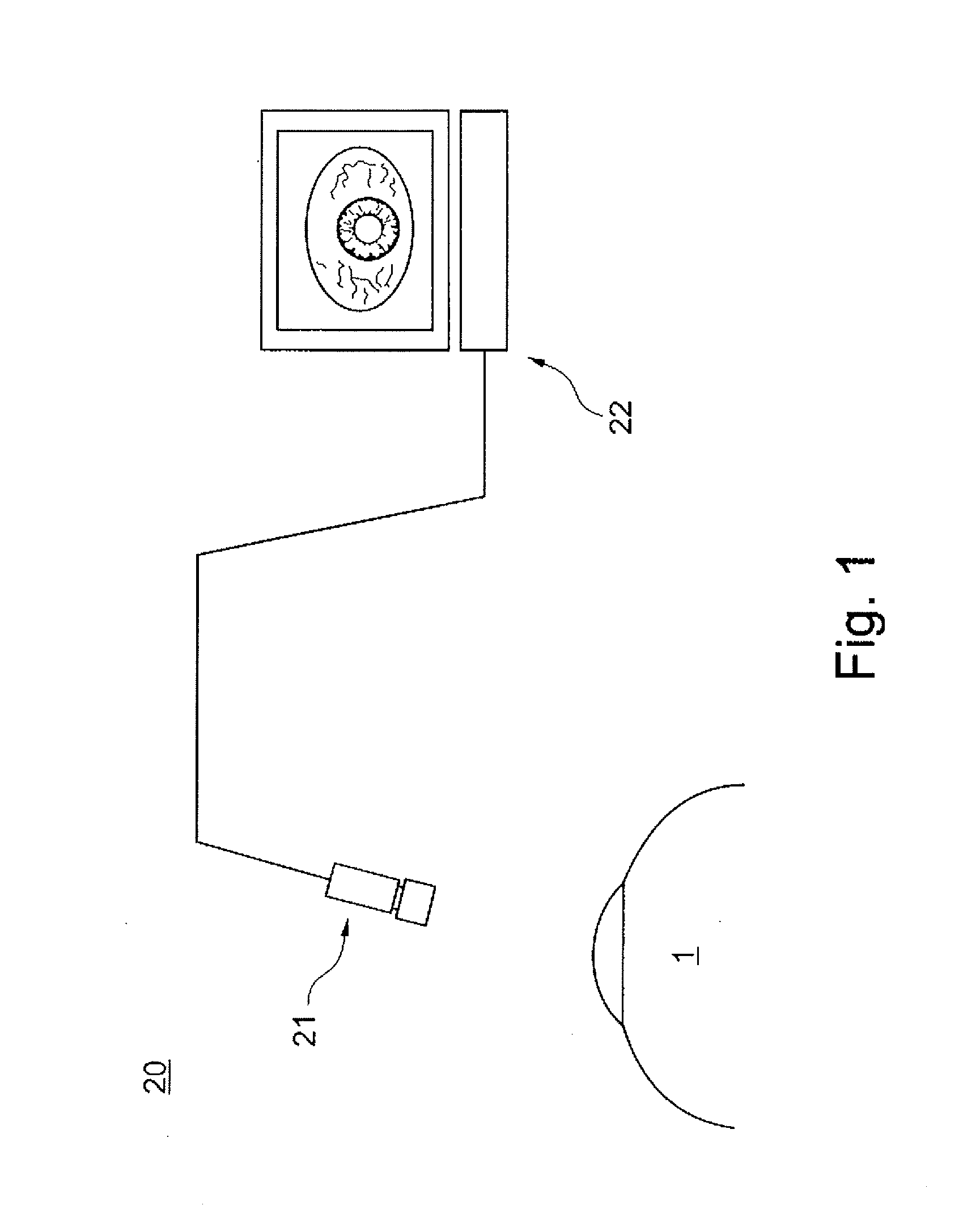
[0021]FIG. 1 shows an example of a device for determining the torsion of an eye;

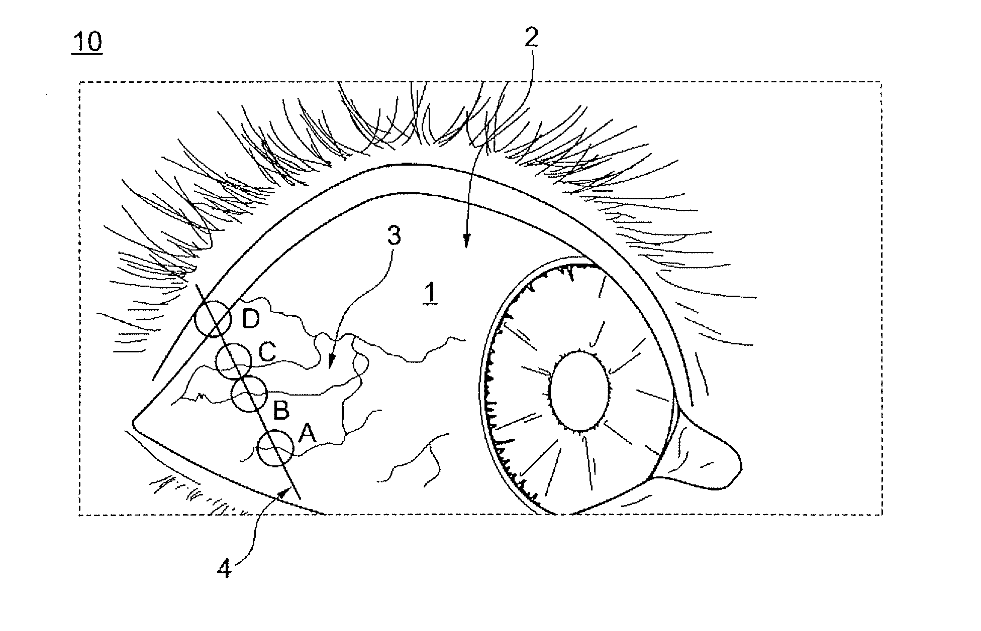
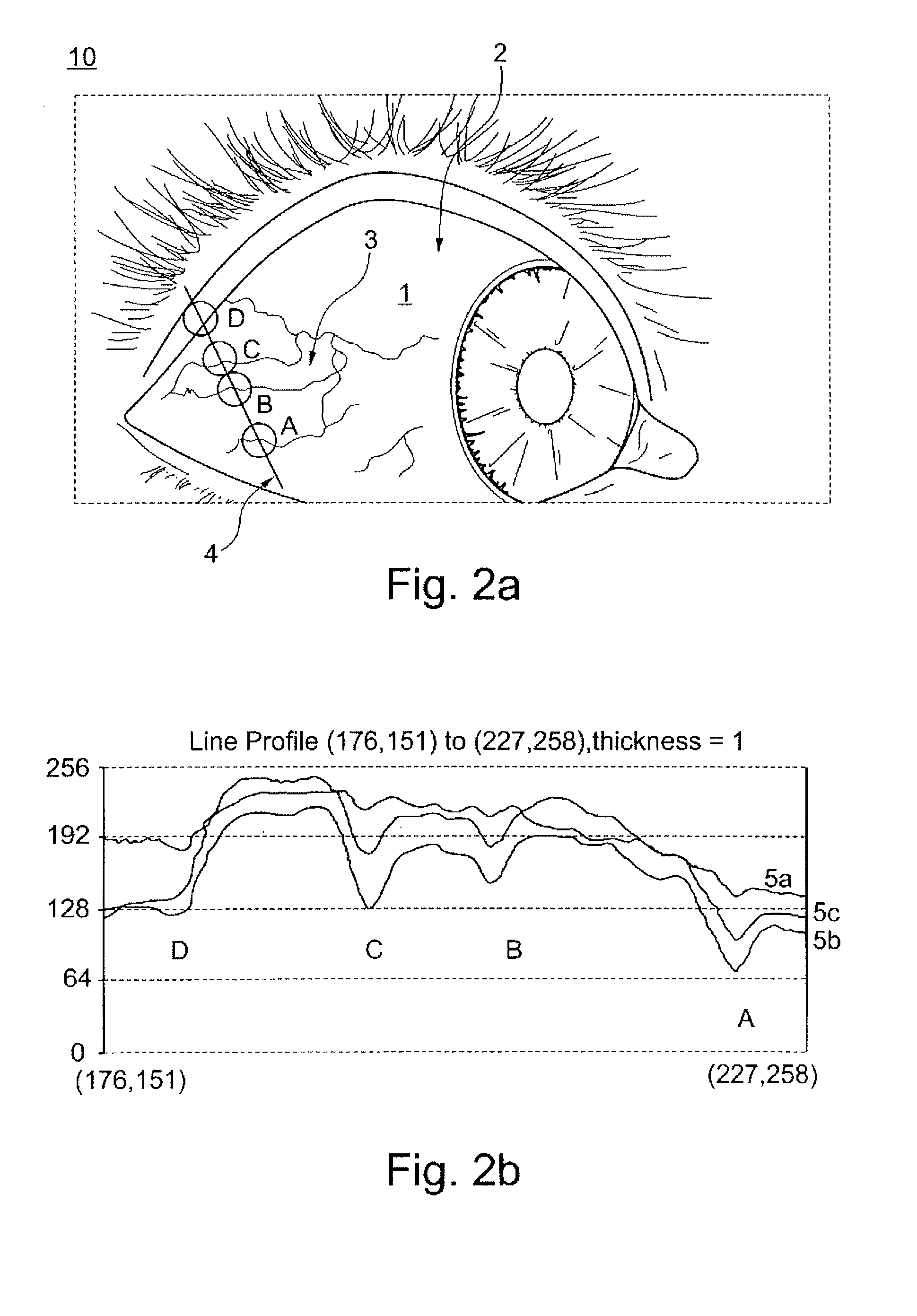
[0022]FIGS. 2a and 2b show an image of an eye captured by a camera and a corresponding colour distribution along a line in the image;

[0023]FIG. 3 shows schematically a histogram of oriented gradients of a blood vessel;

[0024]FIG. 4 shows two histograms of oriented gradients of a blood vessel which are displaced relative to each other, and which are created from two images of the eye;

[0025]FIGS. 5a and 5b show a stylised blood vessel (FIG. 5a) and an appropriate histogram of the normal direction;

[0026]FIGS. 6a and 6b show the stylised blood vessel of FIG. 5a with the corresponding histogram of the normal direction, wherein the blood vessel is rotated by 10 degrees;

[0027]FIG. 7 shows the histograms of FIG. 5b and FIG. 6b for the determination of the torsion of the eye;

[0028]FIG. 8 shows an i...


PUM


Abstract

The invention relates to a device for determining eye torsion, comprising a camera and an image processing unit, which is designed to carry out a method for determining eye torsion. In the method, at least two images of an eye are recorded and image data are produced from said images, and at least one characteristic feature of the eye is identified from the image data, for example a blood vessel. Direction histograms of the feature in both images are produced and compared with each other. The angle of the torsion of the eye is determined from the shift of the directions in the direction histograms.

Description

[0001]The invention relates to a method and a device for determining the eye torsion.BACKGROUND OF THE INVENTION[0002]In the field of medical engineering as well as for equilibrium studies, it is important to determine the torsion of the human eye, i.e. the rotation of the eye around the viewing direction (z-axis). In medical engineering, for example for the insertion of toric intraocular lenses, the rotation of the eye must be known exactly in order to ensure the exact adjustment of the lens in relation to the eye. But also for a laser treatment of the eye or its preparation, the knowledge of torsional movements of the eye leads to a more precise result. Further possible fields of application include neuroscience research or investigations of the effect of images or visual stimulations on the human being, for example in the field of advertisement and communications.[0003]Document DE102006002001 describes a method for determining the spatial relationship of an eye with reference to ...

Claims


Application Information

Patent Timeline
IPC IPC(8): A61B3/14
CPCA61B3/0025A61B3/113A61B3/14G06T2207/30101G06T7/0044G06T2207/30041G06T7/0016G06T7/74
Inventor SPASOVSKI, SASO
Owner CHRONOS VISION
Why Eureka
Try Eureka