LED street lamp

a technology of led lamps and street lamps, which is applied in the direction of fixed installation, lighting and heating equipment, lighting support devices, etc., can solve the problems of deteriorating the brightness of such light rays, high cost, waste, etc., and achieves the effect of reducing costs

Inactive Publication Date: 2013-06-27
POWER DIGITAL DELIGHT
View PDF8 Cites 8 Cited by
  • Summary
  • Abstract
  • Description
  • Claims
  • Application Information

AI Technical Summary

Benefits of technology

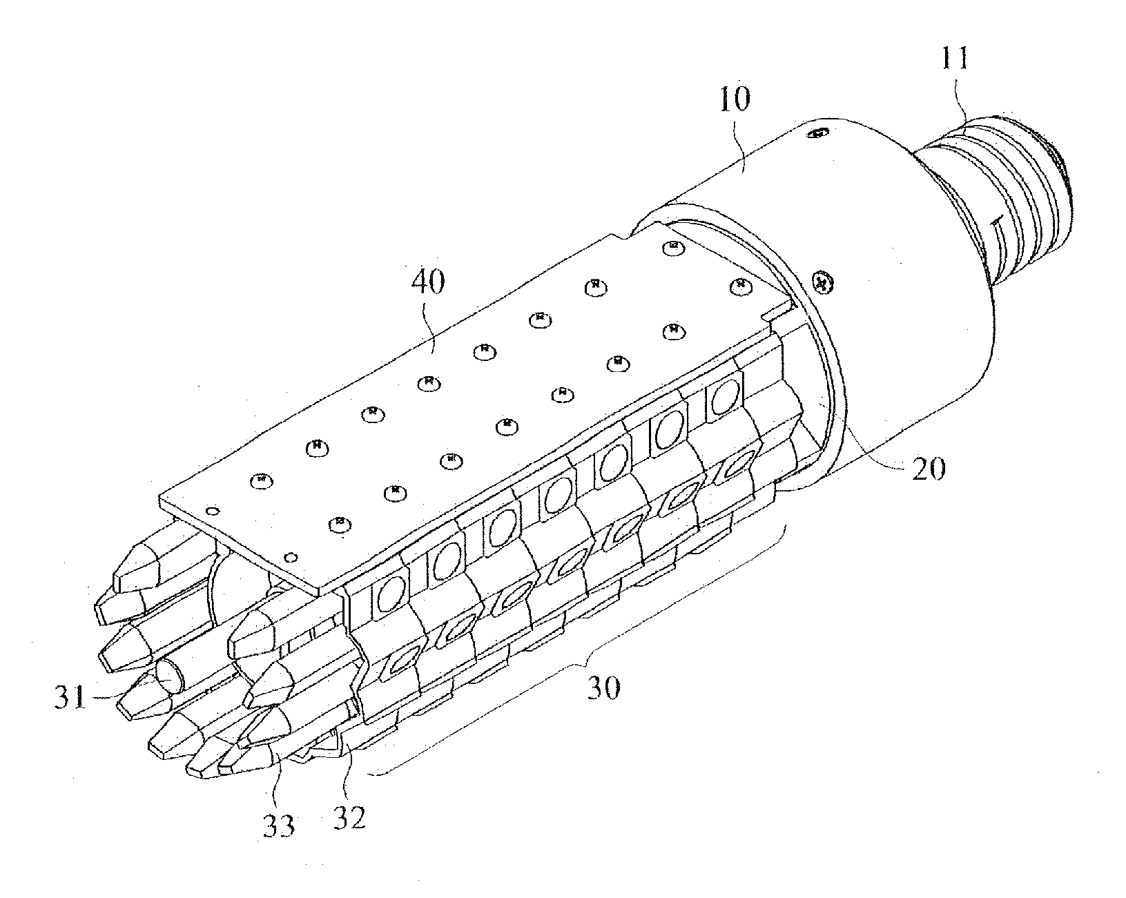
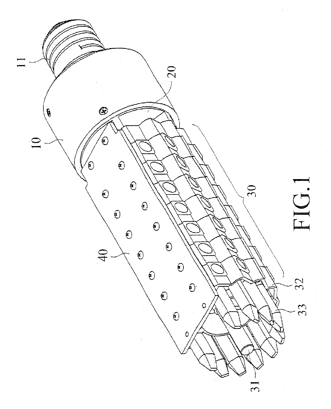
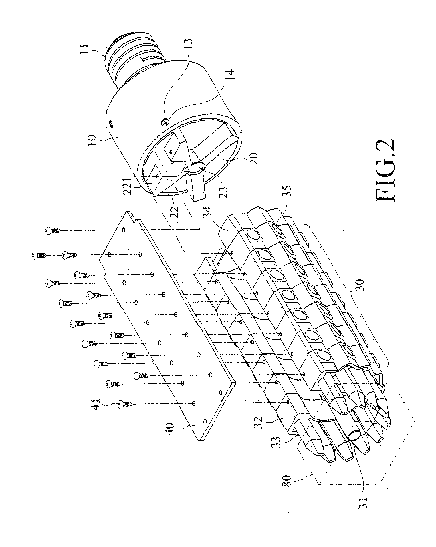
[0004]The primary objective of the present invention is to provide a street lamp, which is constructed by combining heat pipes and lamp components in such a way that each heat pipe has a side surface to which LEDs are mounted so that the heat generated by the LEDs can e immediately dissipated away by the heat pipe to thereby overcome the issue of heat dissipation found in the conventional street lamp and also allows of the use of the existing street lamp to thereby reduce the cost.
[0005]Another objective of the present invention is to provide an arrangement in which a base and a lamp body are allowed to rotate relative to each other and are thus usable in the existing lighting devices and allow of adjustment of light projection direction of the street lamp. Such an arrangement allows the street lamp according to the present invention to be usable in an existing street lamp (such as E39 / E40 or similar standards) to provide a street lamp of which the direction of projection of LED light is adjustable.

Problems solved by technology

This certainly deteriorates the brightness of such light rays.
In addition, although the outside shape of the conventional street lamp is often of such a design as to render low wind resistance and dust- and rain-proofness, yet internal heat dissipation is often very poor.
The whole system of the street lamp must be changed and this is extremely expensive and a waste also.
The overall lighting is poor.

Method used


Image

  • LED street lamp
  • LED street lamp
  • LED street lamp

Examples


second embodiment

[0032]Referring to FIG. 9, a structure of a second embodiment according to the present invention is shown, in which the lamp component 60 comprises a centrally located guide channel 61 and a bearing surface 63 formed in a top portion thereof. However, each of the through holes 621 for the heat pipes and each of the troughs 622 for the lighting modules are combined to form a single inwardly recessed sideway slot 62 that is in communication with the outside, whereby the respective heat pipe 33 and the respective lighting module 35 can be directly inlaid in the sideway slot 62 of the lamp component 60. The overall structural arrangement is illustrated in FIGS. 10 and 11 and it preserves the convenience of use and maintains the feature of the present invention.

[0033]Referring to FIG. 2, a heat dissipation device 80, which can be of any of various means of heat dissipation, such as heat dissipation fins or a heat dissipation fan, can be arranged at an end of the lamp body 30 and coupled ...

third embodiment

[0034]Referring to FIGS. 12 and 13, a structure of the present invention is shown, in which the lamp body 50 comprises a support post 51 mounted at a center thereof and heat pipes 53 that are curved structures arranged at a circumferential portion thereof. In the embodiment illustrated, the heat pipes are of a U-shape having an outside surface forming a flattened surface 531 to which a flexible circuit board 532 is mounted. The flexible circuit board 532 comprises a plurality of spaced LED-based light emission bodies 351, each of which is in combination with a lens assembly 352 to form a lighting module 35.

[0035]A plurality of lamp components 52 is attached, in a cascade form, to the support post 51 and is of the circular or annular structure described above, in which a guide channel 521 is formed in a center thereof and troughs 522 are formed in a side surface thereof. Also, a top portion of each lamp component forms a bearing surface 523. However, a receiving recess 524 is formed ...


PUM


Abstract

An LED street lamp includes a base having an end forming a connection head and an opposite end rotatably coupled to a rotatable LED lamp body. The lamp body includes therein heat pipes to which a flexible circuit board carrying LEDs is mounted. Multiple lamp components are connected in a cascade form to constitute the lamp body, whereby when the LEDs emit light, the heat generated can be dissipated away by the heat pipes. Further, each LED light source is set in a given direction according to a trough defined in the lamp component that receives the LED light source so that uniform and bright lighting can be obtained. The device is connectable to an existing street lamp in order to save the great expense for replacing the whole street lamp.

Description

TECHNICAL FIELD OF THE INVENTION[0001]The present invention generally relates to an LED (Light-Emitting Diode) street lamp that is in compliancy with the existing street lamp specifications, such as E39 / E40 or similar standards.DESCRIPTION OF THE PRIOR ART[0002]With the years' use and experience of street lamps, it is found that the best configuration of a street lamp is that shown in FIG. 15 of the attached drawings, in which a curved metal hood 70 forms an upper portion of the lamp and a curved glass cover 71 is attached under the hood 70. A socket 72 is arranged at an end inside the hood 70 and the cover 71 to receive an E39 / E40 light bulb 90 to screw therein. A shaped post 73 extends from the lamp down to the ground to complete the structure of the street lamp. However, the light bulb 90 of the conventional street lamp emits light in a radiating fashion so that the light rays L2 emitting from an upper portion of the light bulb 90 travels upward first to impinge the hood 70 and i...

Claims


Application Information

Patent Timeline
Patent Type & Authority Applications(United States)
IPC IPC(8): F21V29/00F21V5/04F21V21/00
CPCY02B20/72F21Y2111/005F21K9/13F21V29/006F21K9/23F21Y2107/30F21Y2115/10F21S8/085F21W2131/103F21V29/717
Inventor CHEN, CHIEN-YUANCHUANG, YING-TE
Owner POWER DIGITAL DELIGHT
Why Eureka
Try Eureka