
LED wiring board and light irradiation apparatus

Inactive Publication Date: 2013-06-27
CCS INC
View PDF4 Cites 38 Cited by
  • Summary
  • Abstract
  • Description
  • Claims
  • Application Information

AI Technical Summary

Benefits of technology

The present invention allows for the LED wiring board to be divided into different sizes and used before and after the division. It also simplifies the process of dividing the LED wiring board.

Problems solved by technology

This raises a problem that manufacturing costs of the LED wiring boards increase, which results in an increase in manufacturing costs of the light irradiation apparatuses.
To cut the LED wiring boards of the various sizes, tools for the respective sizes are assumed to be prepared, but there is also a problem that it is difficult to provide the tools for the respective sizes in terms of, for example, costs.
However, operation of the jumper-wiring of each unit board is complicated, which causes an increase in assembly man hours and a problem of wire connection failure, leaving a concern of deteriorated yield rate.
This raises a problem that circuit design needs to be made with a wiring pattern in alignment with the delinking part.
This results in a more significant problem with a more complicated wiring pattern.
There is also a problem that upon cutting of the delinking part, when a tool is used, preparation of a desiccated tool in correspondence with each designated size as described above.
In a case where the user manually performs the cutting without using the tool, there arises a problem that it is difficult to cut it linearly.

Method used


Image

  • LED wiring board and light irradiation apparatus
  • LED wiring board and light irradiation apparatus
  • LED wiring board and light irradiation apparatus

Examples


Embodiment Construction

[0051]Hereinafter, one embodiment of a light irradiation apparatus 100 according to the present invention will be described with reference to the accompanying drawings.

[0052]

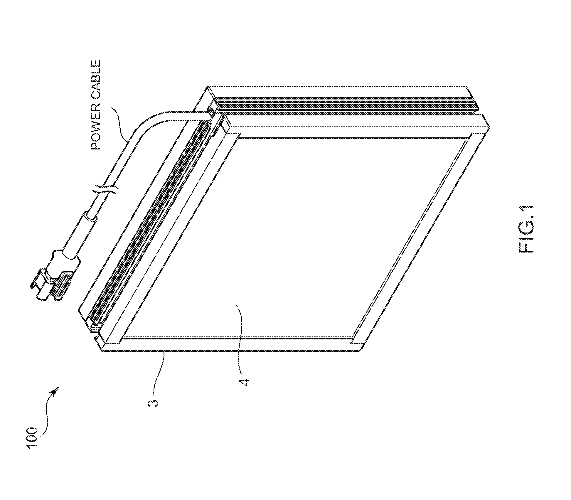
[0053]The light irradiation apparatus 100 according to the present invention, for example, irradiates light to a work in order to perform a surface test on this work, and as shown in FIG. 1, is a surface light-emitting apparatus having a light irradiation surface of a substantially rectangular shape.

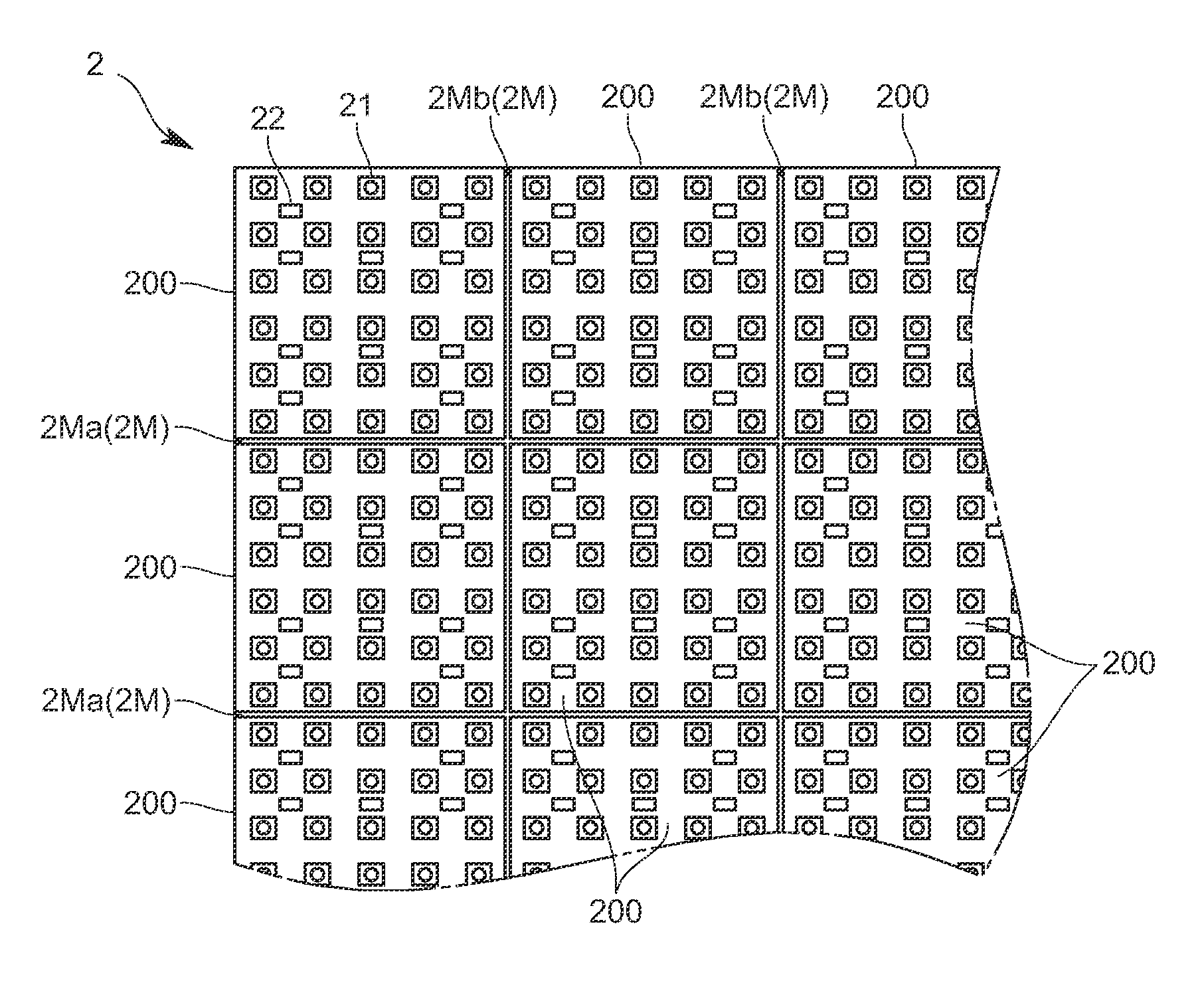
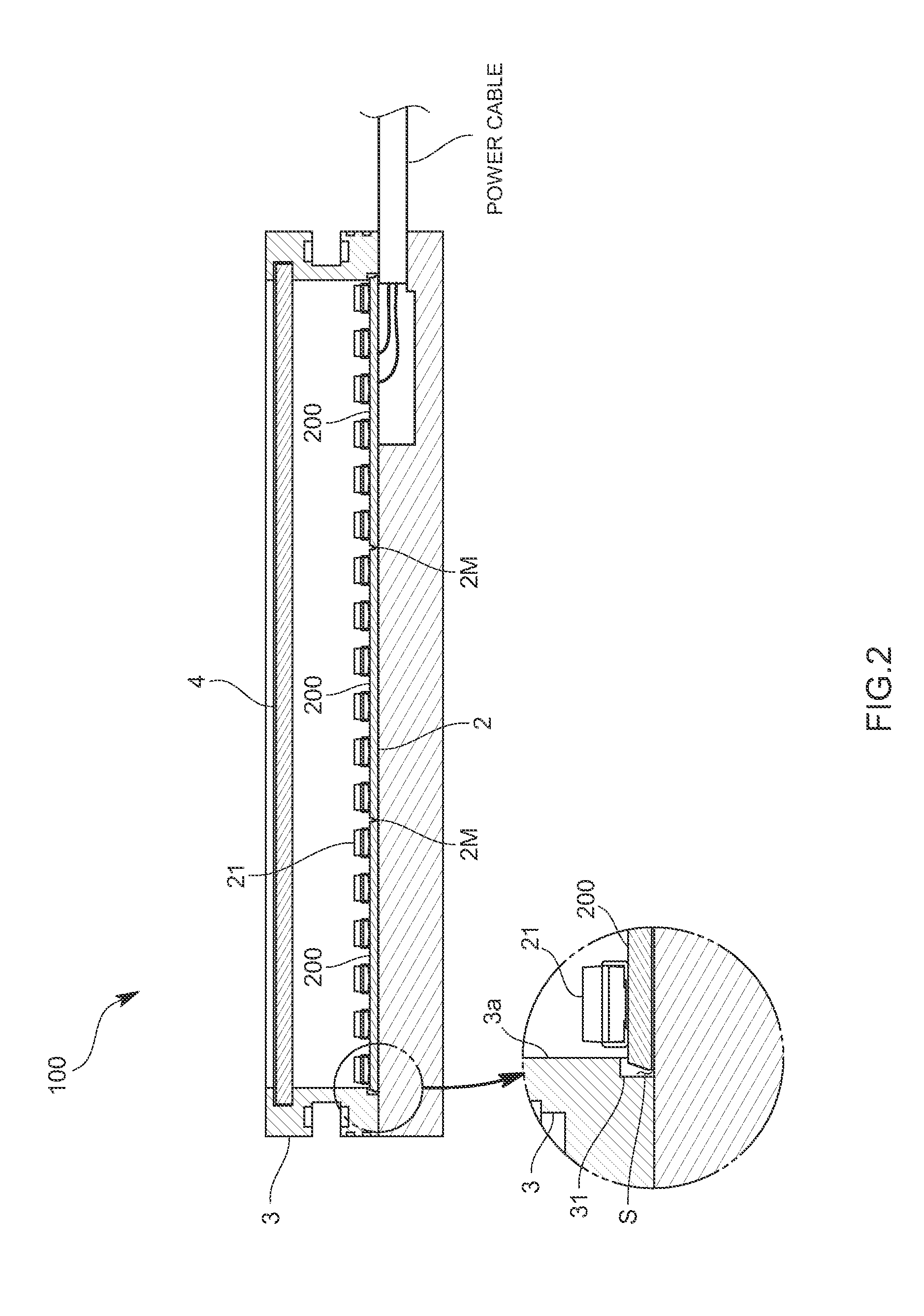
[0054]More specifically, as shown in FIGS. 1 and 2, this includes: an LED wiring board 2 loaded with a plurality of LEDs 21; and a casing 3 having a board storage space for storing this LED wiring board 2. The casing 3 has a bottomed-box-like shape having an opening at one surface. A light-transmitting member 4 such as a lens board having a diffuser plate and a lens part corresponding to each LED is provided.

[0055]The LED wiring board 2 has a substantially rectangular shape in a planar view, and as shown in FIGS. 2 a...


PUM

PropertyMeasurementUnit
Depthaaaaaaaaaa
Depthaaaaaaaaaa
Depthaaaaaaaaaa

Abstract

It is an object of the present invention to permit division of an LED wiring board into various sizes to permit its use before and after the division, and also simplify operation of this division and simplify circuit design. More specifically, in the present invention, wiring patterns and for energizing LEDs are formed in a planar direction of the LED wiring board. Division grooves for dividing the LED wiring board into a plurality of sub-boards are formed on the front surface of the LED wiring board in a perpendicular direction and are provided in a manner such as to cross the wiring patterns in the planar direction. Use with the entire board before the division by the division grooves is possible, and use with division elements divided along any of the division grooves is also possible.

Description

TECHNICAL FIELD[0001]The present invention relates to an LED wiring board loaded with an LED and a light irradiation apparatus using the LED wiring board.BACKGROUND ART[0002]A light irradiation apparatus, for example, a surface light source device includes an LED wiring board loaded with LEDs, and a casing for storing the LED wiring board. Various sizes of such a light irradiation apparatus may be prepared in accordance with intended illumination purposes.[0003]However, the preparation of the light irradiation apparatuses of the various sizes requires preparation of LED wiring boards suitable for the corresponding sizes. This raises a problem that manufacturing costs of the LED wiring boards increase, which results in an increase in manufacturing costs of the light irradiation apparatuses. To cut the LED wiring boards of the various sizes, tools for the respective sizes are assumed to be prepared, but there is also a problem that it is difficult to provide the tools for the respecti...

Claims


Application Information

Patent Timeline
IPC IPC(8): F21V21/00B26D1/24
CPCF21Y2105/001H05K1/0287H05K3/0052H05K2201/0909H05K2201/10106H05K2203/0228F21Y2101/02F21V21/00B26D1/24H05K2201/093H05K2203/175F21Y2105/10F21Y2115/10Y10T83/0581H01L33/62H01L33/48
Inventor MIURA, KENJI
Owner CCS INC
Learn More