Transmission mechanism adapted to an electro-mechanical lock and electro-mechanical lock therewith

a technology of transmission mechanism and electro-mechanical lock, which is applied in the direction of keyhole guards, lock applications, gearing, etc., can solve the problems of reducing the life of the electro-mechanical lock, the gear transmission mechanism is easily worn, and the structural complexity of the gear transmission mechanism, so as to reduce the structural complexity of the pushing member, reduce the wear, and facilitate assembly

Active Publication Date: 2013-07-04
TAIWAN FU HSING INDAL
View PDF8 Cites 26 Cited by
  • Summary
  • Abstract
  • Description
  • Claims
  • Application Information

AI Technical Summary

Benefits of technology

[0009]In summary, when the electro-actuating member (e.g. a motor) drives the pushing member to rotate toward the first direction, the second pushed structure on the pushing member cooperates with the first pushed structure on the bottom board, so that the pushing member is pushed to move relative to the bottom board. In such a manner, by design that the first pushed structure and the second pushed structure for driving the clutch member are respectively disposed on the bottom board and the pushing member, the present invention can reduce structural complexity of the pushing member, so as to facilitate assembly, In addition, when the electro-actuating member drives the pushing member, the present invention utilizes the bottom board to provide a reaction force required to push the clutch member. Since the bottom board can be fixed on a door, the present invention can reduce wearing by increasingly improve stability of mechanism when functioning. As a result, it enhances life of the electro-mechanical lock and thus advantages the electro-mechanical lock in the market.

Problems solved by technology

It results in structural complexity of the gear transmission mechanism and disadvantages of assembly.
Moreover, when the gear transmission mechanism drives the clutch mechanism, the gear transmission mechanism is also exerted by a reaction force applied by the clutch mechanism, resulting in that the gear transmission mechanism is easily worn.
As a result, it reduces life of the electro-mechanical lock and thus disadvantages the electro-mechanical lock in the market.

Method used


Image

  • Transmission mechanism adapted to an electro-mechanical lock and electro-mechanical lock therewith
  • Transmission mechanism adapted to an electro-mechanical lock and electro-mechanical lock therewith
  • Transmission mechanism adapted to an electro-mechanical lock and electro-mechanical lock therewith

Examples


Embodiment Construction

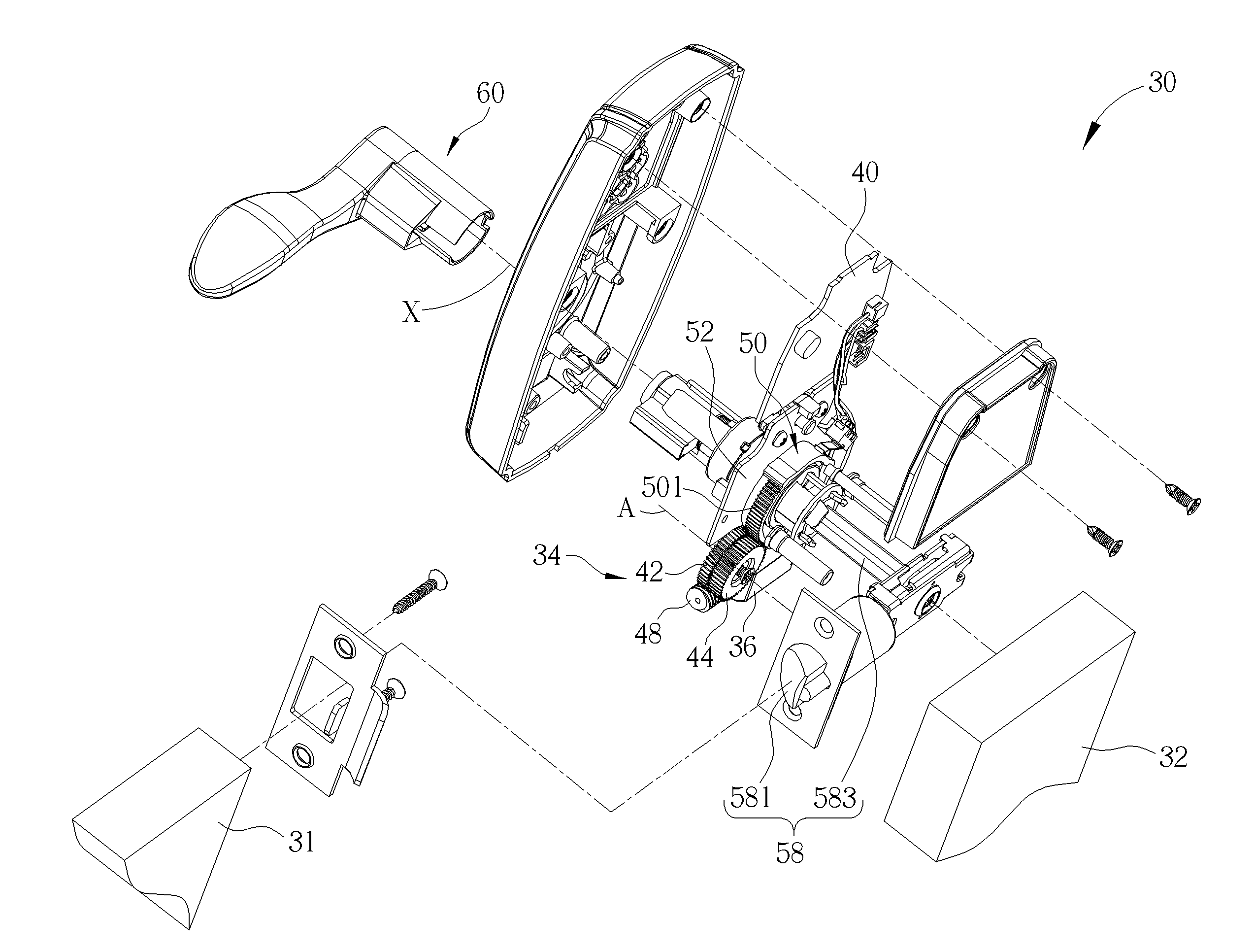
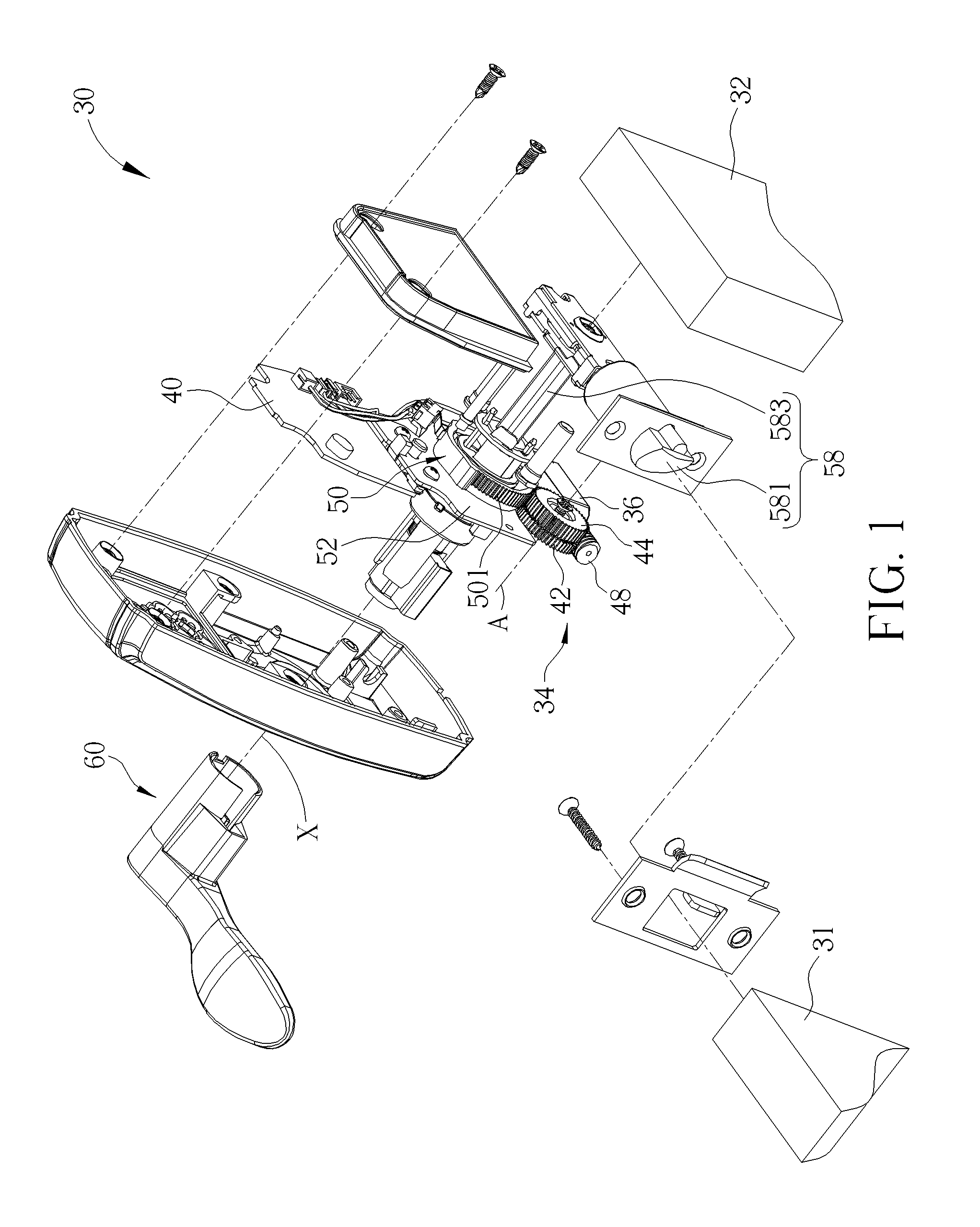
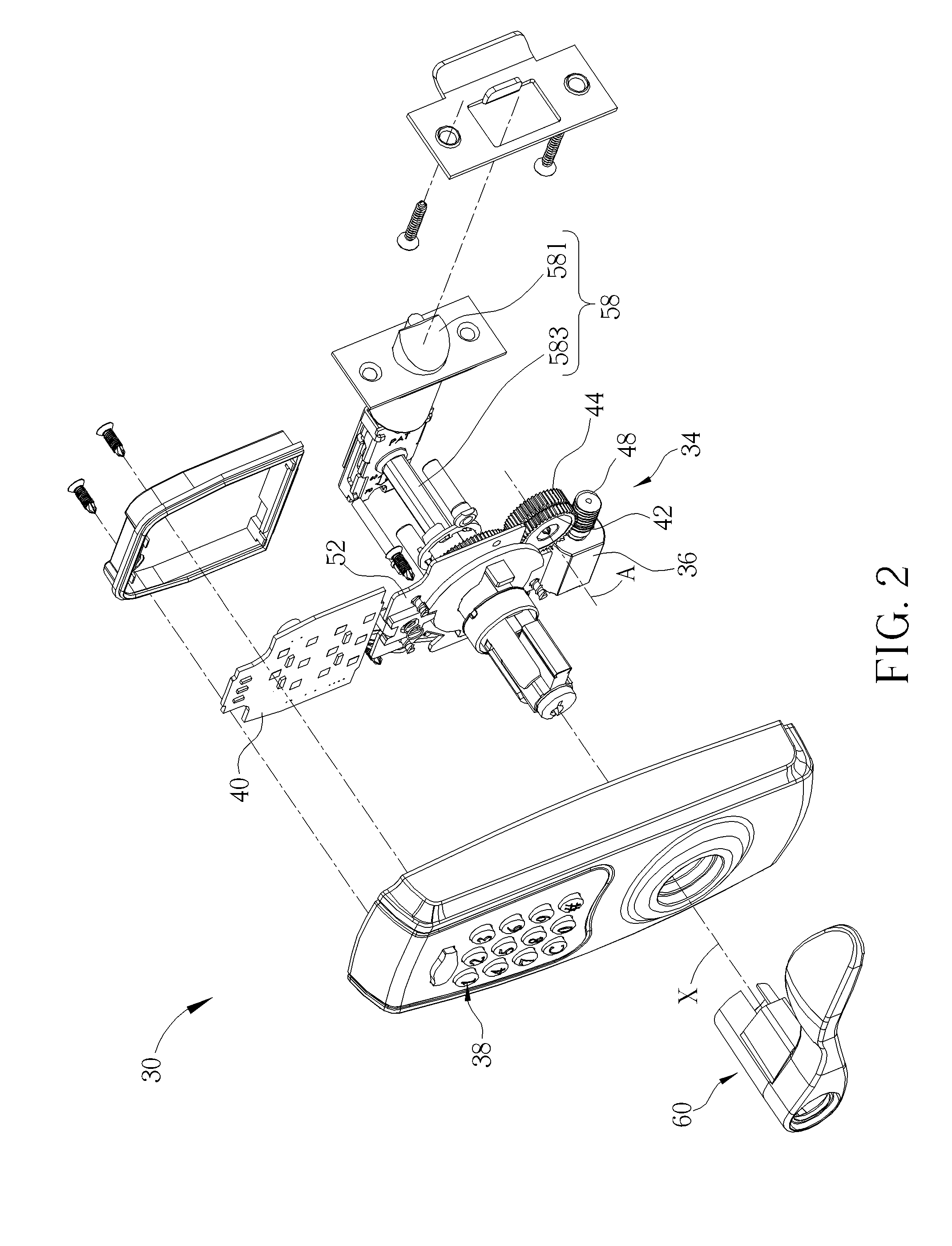
[0038]Please refer to FIG. 1, which is a diagram of an electro-mechanical lock 30 according to an embodiment of the present invention. As shown in FIG. 1, the electro-mechanical lock 30 could be installed on a door 32 for locking the door 32 onto a wall 31 or for unlocking the door 32 from the wall 31, so that the door 32 could be correspondingly in a locked status or an unlocked status. Please refer to FIG. 1 and FIG. 2. FIG. 2 is a diagram of the electro-mechanical lock 30 at another viewing angle. As shown in FIG. 1 and FIG. 2, the electro-mechanical lock 30 includes a transmission mechanism 34. The transmission mechanism 34 includes an electro-actuating member 36. The electro-actuating member 36 is used as the power source of the electro-mechanical lock 30. Furthermore, the electro-mechanical lock 30 further includes an input unit 38 for inputting a signal, such as a password signal. In this embodiment, the input unit 38 could be a button device, but not limited thereto. For exa...


PUM


Abstract

A transmission mechanism adapted to an electro-mechanical lock and for driving a latch assembly to be unlocked is disclosed. The transmission mechanism includes a bottom plate, a pushing member, a clutch member and an electro-actuating member. The bottom plate includes at least one first pushed structure. The pushing member includes at least one second pushed structure. The clutch member abuts against the pushing member. The electro-actuating member is for driving the pushing member to rotate toward a first direction. The at least one second pushed structure cooperates with the at least one first pushed structure to move the pushing member relative to the bottom board, so that the clutch member is pushed with movement of the pushing member to an unlocked position.

Description

BACKGROUND OF THE INVENTION[0001]1. Field of the Invention[0002]The present invention relates to a transmission mechanism adapted to an electro-mechanical lock and an electro-mechanical lock therewith, and more particularly, to a transmission mechanism for driving the latch assembly to be in an unlocked status and an electro-mechanical lock therewith.[0003]2. Description of the Prior Art[0004]Generally speaking, an electro-mechanical lock utilizes a gear transmission mechanism to transmit a torsion torque outputted by a motor, so as to drive a clutch mechanism of the electro-mechanical lock to engage with or disengage from a latch assembly. When the gear transmission mechanism is forwardly driven by the motor, a pushed structure on the gear transmission mechanism can drive the clutch mechanism to engage with the latch assembly of the electro-mechanical lock. Accordingly, a torsion torque exerted by a handle can be transmitted to the latch assembly, so that a user can open the door b...

Claims


Application Information

Patent Timeline
Patent Type & Authority Applications(United States)
IPC IPC(8): E05B47/00F16H19/02E05B49/00
CPCE05B47/0012E05B47/068E05B63/04E05B13/101E05B2047/002Y10T74/18056E05B47/0001E05B49/00F16H19/02E05B2047/0026E05B2047/0031Y10T70/7068Y10T292/57
Inventor HUANG, LIEN-HSIHUANG, JIAN-YUAN
Owner TAIWAN FU HSING INDAL
Why Eureka
Try Eureka