Pneumatic radial tire for a passenger vehicle

a passenger vehicle and pneumatic technology, applied in vehicle components, road transportation emission reduction, rolling resistance optimization, etc., can solve the problems of degrading interior comfort, fuel consumption becoming worse, and rolling resistance being reduced, so as to achieve uneven wear resistance and low fuel consumption. , the effect of good wear resistan

Inactive Publication Date: 2013-07-04
BRIDGESTONE CORP
View PDF3 Cites 6 Cited by
  • Summary
  • Abstract
  • Description
  • Claims
  • Application Information

AI Technical Summary

Benefits of technology

[0014]According to the present invention, it is possible to provide a pneumatic radial tire for a passenger vehicle with a reduction of coefficient of (value

Problems solved by technology

In addition, because the high rigidity of the crown portion suppresses a transmission of motions of tire constituting members, the rolling resistance is reduced.
However, the larger tire width

Method used


Image

  • Pneumatic radial tire for a passenger vehicle
  • Pneumatic radial tire for a passenger vehicle
  • Pneumatic radial tire for a passenger vehicle

Examples


Embodiment Construction

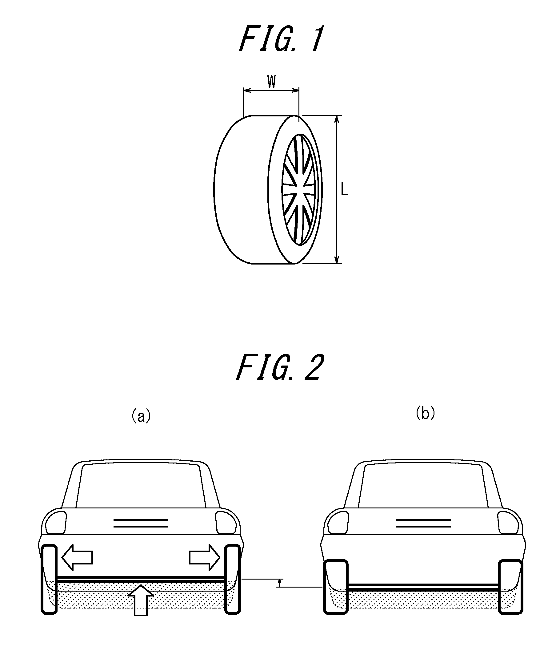
[0029]The following describe the processes led to the development of a pneumatic radial tire for a passenger vehicle according to the present invention. First, the inventor focused attention on the section width W of the radial tire as shown in FIG. 1, and has found that, by narrowing the cross-section-width W as compared to the conventional tire, as shown in FIG. 2, an interior space, especially a space for arranging drive components near the inside of the tire installed on the vehicle can be ensured. In addition, a tire with a narrower section-width W has a smaller area as viewed from the front of the tire (hereinafter referred to as the front projection area), which results in an effect of reducing the air resistance of the vehicle. However, it involves a larger deformation of the ground contact portion, which causes a problem that the tire has larger rolling resistance under the same air pressure.

[0030]Further, the inventor has found that the peculiar nature of the radial tire m...


PUM


Abstract

A pneumatic radial tire for a passenger vehicle has a ratio W/L where W is a cross-sectional width and L is an outer diameter. The tire also has a belt-reinforcing layer having a high rigidity and disposed between a belt and a tread.

Description

TECHNICAL FIELD[0001]The present invention relates to a pneumatic radial tire for a passenger vehicle, and more particularly for a tire used for an electronic vehicle simultaneously improving low fuel consumption, interior comfort and an uneven wear resistance.RELATED ART[0002]Until the 1960s, vehicles were lighter, and the speed demanded for the vehicles were lower, resulting a less burden on the tires were less. Therefore, bias tires with narrower section widths had been used. Today, due to heavier weight and higher speed of vehicles, tires having a radial structure and a larger width have been more widely manufactured (see Patent Document 1). A tire applied with a radial carcass has an excellent uneven wear resistance due to higher rigidity of the tire crown portion as compared with a bias tire. In addition, because the high rigidity of the crown portion suppresses a transmission of motions of tire constituting members, the rolling resistance is reduced. For this reason, the radi...

Claims


Application Information

Patent Timeline
IPC IPC(8): B60C3/04
CPCB60C3/04B60C11/0332B60C2009/2266B60C9/2009B60C9/2204Y02T10/86
Inventor KUWAYAMA, ISAO
Owner BRIDGESTONE CORP
Why Eureka
Try Eureka