Antenna device and communication device

Inactive Publication Date: 2013-07-04
DEXERIALS CORP
8 Cites 23 Cited by

AI-Extracted Technical Summary

Problems solved by technology

As can be seen in FIG. 13, for the inductance L20 at 20° C. as the design center, a shift occurs in each magnetic sheet approximately by 1.0% to 2.0% at maximum in a temperature range of −20° C. to 60° C., disadvantageously resulting in a large shift in resonance frequency.
For the...

Method used

[0070]In FIG. 8, as an actually measured value (KM30) and a calculated value substantially matching the actually measured value (KM30), the following two calculated values are depicted. That is, these calculated values are those obtained by adding weights of 13% and 11.5% each as a contribution ratio with respect to the actually measured values of the FPC (single) to the calculated values, which are characteristic values using the troidal ring depicted in FIG. 7. As evident from this F...

Benefits of technology

[0019]In the present invention, the magnetic sheet is formed so as to be superposed on the antenna coil, the magnetic sheet having the temperature characteristic of changing the inductance of the antenna coil so as to achieve the characteristic inverse to the change of the inductance of the antenna coil with the temperature change in the use temperature range and substantially matching the resonance frequency of the resonant circuit with the oscillation frequency in the use temperature region. As such, in the present invention, the change of the reson...

Abstract

An antenna device, capable of stable communications without increasing a space of the entire device by keeping a resonance frequency substantially constant even if the temperature changes, includes: an antenna circuit having an antenna coil with an electrically connected capacitor; the coil receiving a magnetic field transmitted from a reader/writer at a predetermined oscillation frequency; the circuit becoming communicable when inductively coupled to the reader/writer; and a magnetic sheet formed at a position superposed on the coil to change its inductance, wherein the coil has a temperature characteristic in which the inductance is changed with a temperature change, and the sheet has a temperature characteristic of changing the inductance to achieve a characteristic inverse to the inductance change with the temperature change in a predetermined use temperature range, and substantially matching a resonance frequency of the circuit with the oscillation frequency in the use temperature region.

Application Domain

Technology Topic

Image

  • Antenna device and communication device
  • Antenna device and communication device
  • Antenna device and communication device

Examples

  • Experimental program(1)

Example

Example 1
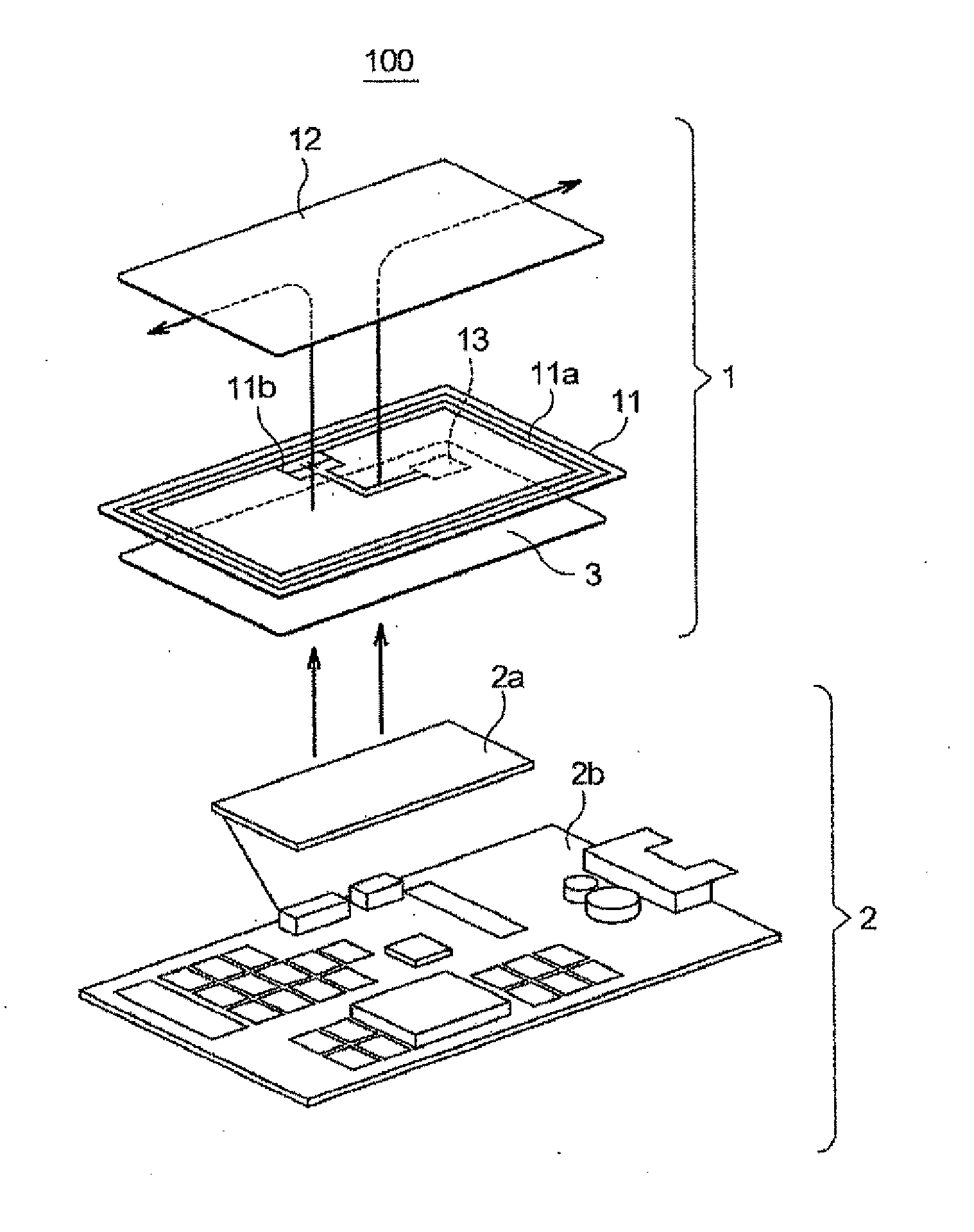
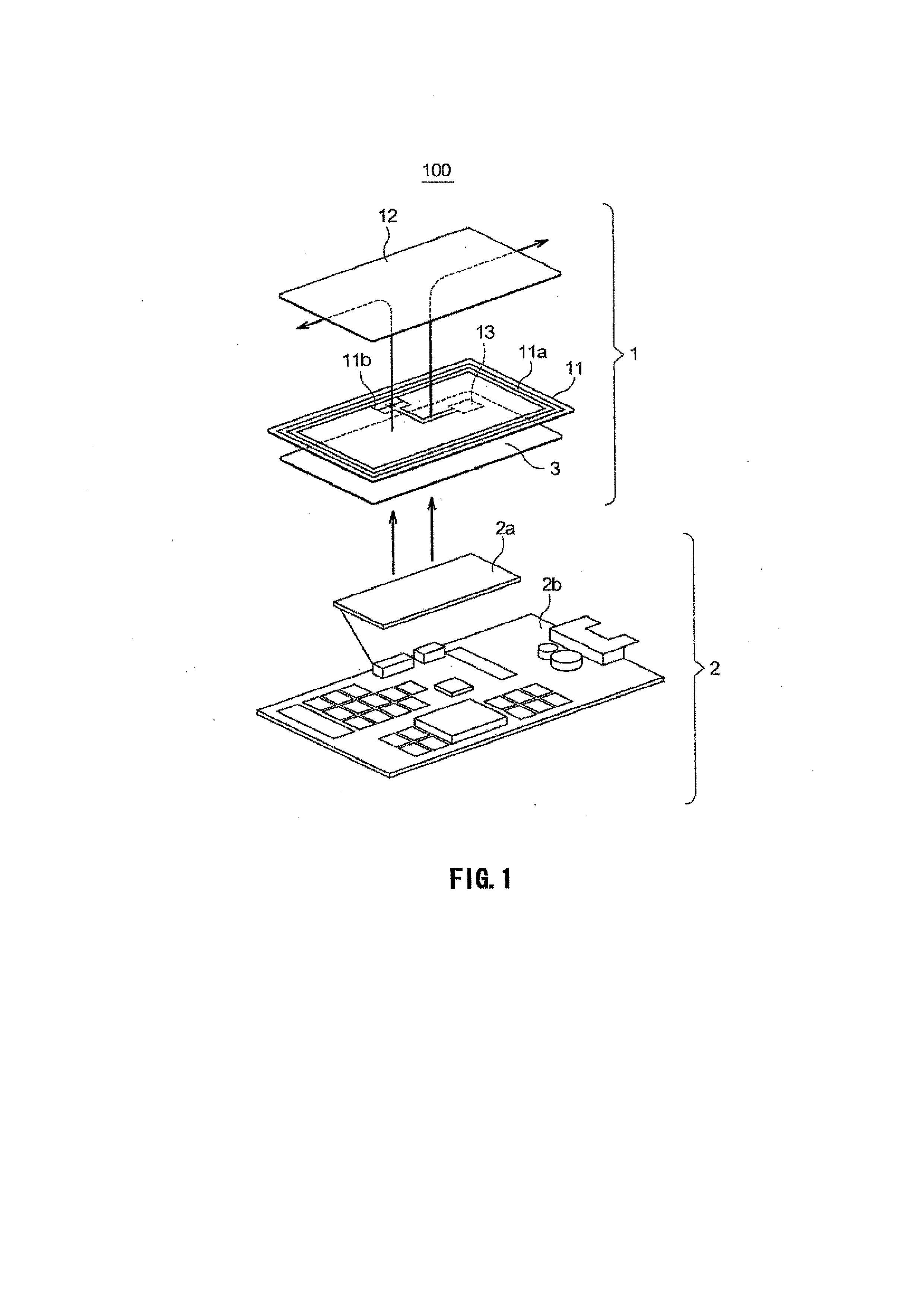
[0064]As a specific example of an antenna module to be incorporated in a portable phone or the like, an antenna module as follows was used. That is, as the antenna coil 11a, one fabricated by a patterning process on a flexible printed board 11c having an outer shape of 36 [mm]×29 [mm] and a thickness of 0.09 [mm] as depicted in FIG. 4A was used. Also, as the magnetic sheet 12, a ferrite having an outer shape of 36 [mm]×29 [mm] and μ′=119 and μ″=1.33 with a frequency of 13.56 MHz as depicted in FIG. 4B was used. Also, the flexible printed board 11c where the antenna coil 11a is fabricated and the magnetic sheet 12 are assumed to be coupled via an acrylic-based ADH sheet having a thickness of 0.3 mm as an adhesive.
[0065]First, FIG. 5 depicts the results of measurement of the temperature characteristic of the inductance of each antenna coil 11a in the case of the single flexible printed board 11c without having the magnetic sheet 12 coupled thereto, the number of windings being 3, 5, and 10, and Cu being used as a conductor wire. This FIG. 5 depicts that the vertical axis represents temperature and the horizontal axis represents values of a difference ratio (Lx−L20)×100/L20 of an inductance Lx with temperature changes with respect to an inductance L20 at 20° C., which is a designed center. Note that legends in FIG. 5 of “3t”, “5t”, and “10t” represent that the number of windings of the antenna coil 11a is 3, 5, and 10, respectively.
[0066]As depicted in FIG. 5, the inductances of all three types of antenna coils 11a are monotonously increased with temperature changes. In particular, among all three types of antenna coils 11a, a change of the inductance of the antenna module having a large number of windings with respect to temperature is relatively large. This is because Cu, which is a conductor wire of the antenna coil 11a, has a relatively large coefficient of linear expansion a of 16.5 and the inductance L represented by L=AN2S is changed with a change of an area S of the antenna coil 11a with a change of a pattern length with respect to temperature. Here, A represents a factor of proportionality and N represents the number of windings.
[0067]Next, since an inductance of the magnetic sheet 12 cannot be measured as a single, it is assumed that, for example, a ring 4 is fabricated by processing the magnetic material of the magnetic sheet 12 into a toroidal ring shape having an inner diameter of 3 mm±0.03 mm, an outer diameter of 7 mm±0.03 mm, and a thickness of 0.1 mm±0.01 as depicted in FIG. 6A, a conductor wire 5 is wound around this ring 4 as depicted in FIG. 6B, and then an inductance is measured when a signal of 13.56 MHz is let flow through the conductor wire. The inductance measured in this manner can be evaluated as a characteristic value of the magnetic material.
[0068]For temperature compensation of the inductance of the antenna coil 11a by utilizing measurement using this troidal ring, as a specific example of the ferrite with the Sb oxide and the Co oxide contained in the Ni—Zn—Cu-based magnetic material, it is assumed that a magnetic material having a temperature characteristic as depicted in FIG. 7 is used. In the magnetic sheet according to this example, the ferrite containing 1.2 weight % of the Sb oxide in Sb2O3 terms and 0.2% of the Co oxide in CoO terms was used. This is an example satisfying the condition that the magnetic material contains 0.7 weight % to 1.25 weight % of the Sb oxide in Sb2O3 terms and 0 to 0.2 weight % of the Co oxide in CoO terms. That is, it is assumed to use a magnetic material KM30 having a temperature characteristic as depicted in FIG. 7 in which a secondary peak is present near −10° C. and the inductance is monotonously decreased with temperature changes higher than the secondary peak. Here, FIG. 7 depicts the temperature characteristic of the inductance of the antenna coil 11a with the single flexible printed board 11c described above and the number of windings being 10, and depicts a temperature characteristic of the inductance of the magnetic material KM30 measured by the troidal ring, with 1/10 of a scaling factor of the vertical axis with respect to this temperature characteristic.
[0069]In the antenna module 1 according to the present example, with the magnetic sheet 12 made of this magnetic material KM30 being coupled via the ADH sheet having a thickness of 0.3 mm to the flexible printed board 11c where the antenna coil 11a having the number of windings of 10 described above is fabricated, the inductance of the antenna coil 11a can be kept constant in a temperature region of at least −10° C. to 40° C., as depicted in FIG. 8.
[0070]In FIG. 8, as an actually measured value (KM30) and a calculated value substantially matching the actually measured value (KM30), the following two calculated values are depicted. That is, these calculated values are those obtained by adding weights of 13% and 11.5% each as a contribution ratio with respect to the actually measured values of the FPC (single) to the calculated values, which are characteristic values using the troidal ring depicted in FIG. 7. As evident from this FIG. 8, the magnetic sheet 12 influences the temperature characteristic of the inductance of the antenna coil 11a by approximately 11.5% to 13%. As evident from these results, by using the characteristic values obtained by using the troidal ring, it is possible to easily achieve a design in which the degree of temperature compensation with respect to the inductance of the antenna coil 11a is evaluated and the temperature characteristics of the inductances substantially match each other.
[0071]Note that the secondary peak is on the order of −20° C. and the magnetic sheet 12 made of a ferrite having a temperature characteristic that the inductance is monotonously decreased to the proximity of 60° C. at a temperature equal to or higher than this secondary peak can be achieved by causing the Ni—Zn—Cu-based magnetic material described above to contain a Sb oxide and a Co oxide under the predetermined condition. Therefore, in the temperature range of −20° C. to 60° C., the inductance of the antenna coil 11a can be kept constant.
[0072]Here, as depicted in FIG. 9, changes of the inductance when the coupling distance between the magnetic sheet 12 and the antenna coil 11a is changed by changing the thickness of the ADH sheet 11d are described. This FIG. 9 is a diagram depicting a sectional shape of the antenna module 1, with a total value of the thickness of the flexible printed board 11c and the thickness of the ADH sheet 11d being taken as a and the thickness of the ADH sheet 11d being taken as b.
[0073]FIG. 10 is a diagram depicting changes of the inductance when the thickness b of the ADH sheet 11d is changed. As evident from this FIG. 10, when the coupling distance between the magnetic sheet 12 and the antenna coil 11a is increased, the inductance is monotonously decreased and, contrarily, when this coupling distance is decreased, the inductance is increased because the magnetic flux generated from the antenna coil 11a is strongly influenced by the magnetic sheet 12. Specifically, when the thickness b is taken as a variable x, an approximation function y of the inductance is represented as y=−0.0015x+3.1622 Here, a square R2 of a similarity index R is 0.9938.
[0074]Also, in the temperature range of at least −10° C. to 40° C., with the magnetic sheet 12 and the flexible printed board being coupled to each other to keep the inductance of the antenna coil 11a constant, the temperature characteristics of the inductance of the antenna coil 11a are depicted in FIG. 11A where a total value of thicknesses of the flexible printed board 11c and the ADH sheet 11d is set as 255 μm, 155 μm, and 55 μm.
[0075]As evident from this FIG. 11A, as a clearance distance between the magnetic sheet 12 and the antenna coil 11a is shorter, the temperature change characteristic of the inductance tends to be intensified.
[0076]As such, in the antenna module 1, by adjusting the clearance distance between the magnetic sheet 12 and the antenna coil 11a, a change of the inductance with a temperature characteristic allowed with upper and lower limit values of the use temperature range can be adjusted.
[0077]Also, under the condition that the total value a of the thicknesses described above is set as 255 μm, FIG. 11B depicts a temperature change characteristic of the inductance when the magnetic sheet 12 made of a magnetic material KM30 is used according to the present example and a temperature change characteristic of the inductance when a magnetic sheet made of a magnetic material KM11 as depicted in FIG. 13 is used as a comparative example.
[0078]Still further, under the condition that the total value a of the thicknesses described above is set as 55 μm, FIG. 11C depicts a temperature change characteristic of the inductance when the magnetic sheet 12 made of the magnetic material KM30 is used according to the present example and a temperature change characteristic of the inductance when the magnetic sheet made of the magnetic material KM11 as depicted in FIG. 13 is used as the comparative example.
[0079]As evident from these FIG. 11B and FIG. 11C, for example, compared with the conventional example using the magnetic sheet made of the magnetic material KM11, the antenna module 1 according to the present example can suppress the temperature change characteristic of the inductance that tends to be increased due to a decrease of the clearance distance between the magnetic sheet 12 and the antenna coil 11a.

PUM

no PUM

Description & Claims & Application Information

We can also present the details of the Description, Claims and Application information to help users get a comprehensive understanding of the technical details of the patent, such as background art, summary of invention, brief description of drawings, description of embodiments, and other original content. On the other hand, users can also determine the specific scope of protection of the technology through the list of claims; as well as understand the changes in the life cycle of the technology with the presentation of the patent timeline. Login to view more.

Similar technology patents

Robot remote communication system

InactiveCN110568785AEasy to control the robot remotelyStable communicationProgramme controlComputer controlGsm moduleWireless
Owner:安徽玄离智能科技股份有限公司

Classification and recommendation of technical efficacy words

Why Eureka
Try Eureka