Sheet Feeding Device and Image Scanning Device Employing the Same

Active Publication Date: 2013-07-04
BROTHER KOGYO KK
View PDF6 Cites 18 Cited by
  • Summary
  • Abstract
  • Description
  • Claims
  • Application Information

AI Technical Summary

Benefits of technology

[0016]When such a sheet feed/discharge tray is used, if a tray surface is arranged higher than the sheet passing surface, the original sheet may not be hooked when the sheet is fed inside a device, while the leading end of the sheet may be hooked easily when the sheet is

Problems solved by technology

The similar problem occurs on the sheet discharging side.
When the same tray is used for the both purposes, it is difficult to optimize the direction of the stepped surface referring to the sheet feeding direction.
Therefore, when the same tray is used for th

Method used


Image

  • Sheet Feeding Device and Image Scanning Device Employing the Same
  • Sheet Feeding Device and Image Scanning Device Employing the Same
  • Sheet Feeding Device and Image Scanning Device Employing the Same

Examples


Embodiment Construction

[0032]Hereinafter, referring to the accompanying drawings, an embodiment according to the invention will be described.

[0033]Structure of MFP (Multi-Function Peripheral)

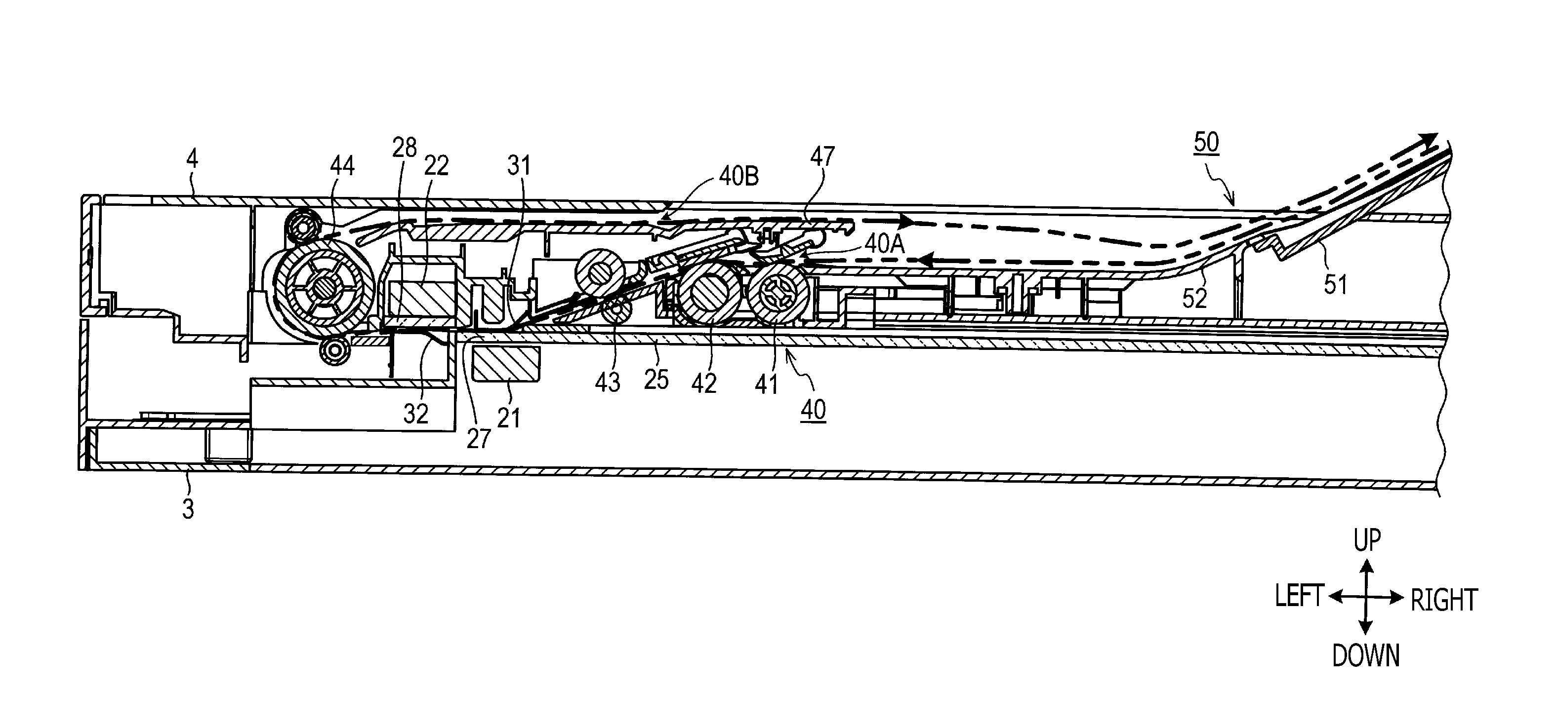
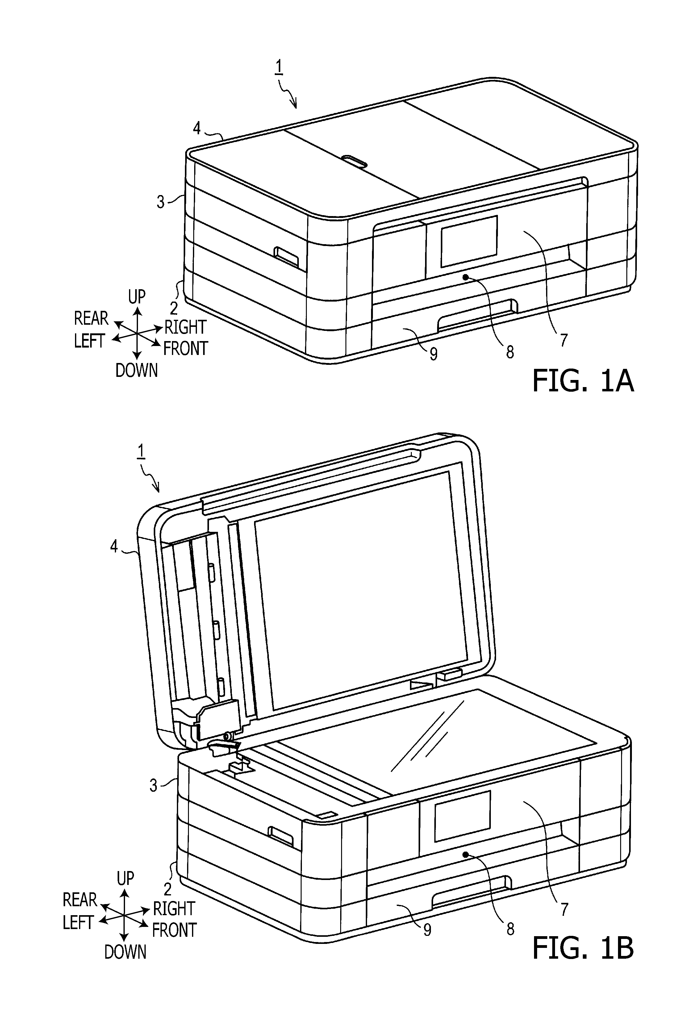
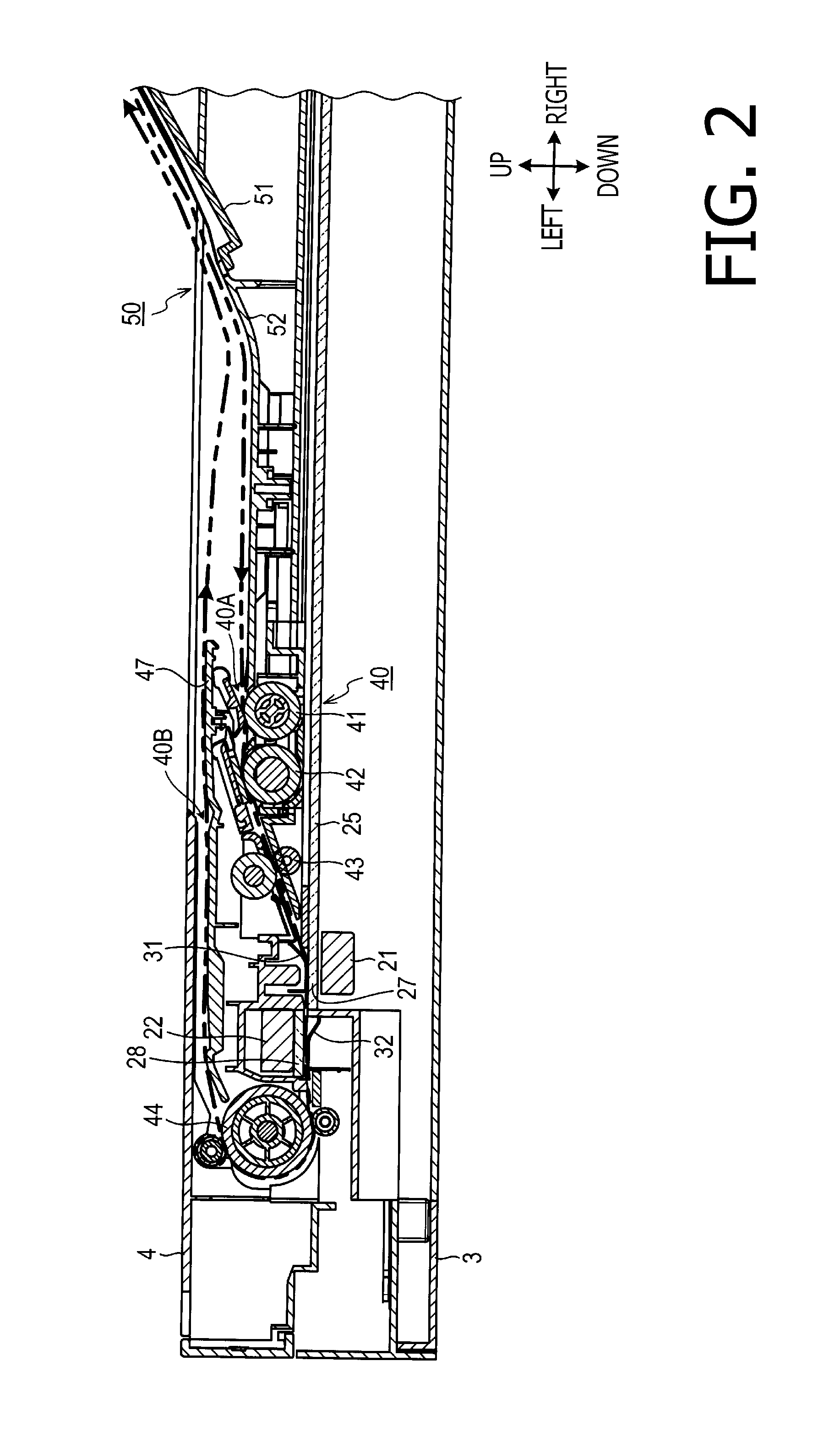
[0034]As shown in FIGS. 1A and 1B, an MFP (multi-function peripheral) 1 is provided with a main unit 2, a scanning unit 3 mounted above the main unit 2, and an original sheet feed unit 4 provided above the scanning unit 3.

[0035]The main unit 2 includes an image forming section, a controller section and power unit. Each mechanism provided in the main unit 2, the scanning unit 3 and the original sheet feeding unit 4 is controlled by the controller section provided to the main unit 2.

[0036]The scanning unit 3 is configured to be rotatable with respect to the main unit 2 about an axis that extends in a right-and-left direction at a rear end portion of the main unit 2 and a rear end portion of the scanning unit 3. When the scanning unit 3 is rotated so that the front end portion of the scanning unit 3 is displaced upward, ...


PUM

PropertyMeasurementUnit
Thicknessaaaaaaaaaa

Abstract

A sheet feeding device is formed with a sheet mounting part, and a sheet feeding unit defining a sheet feed path having inlet and outlet. The sheet feeding unit is configured to introduce the sheet on the sheet mounting surface from the inlet, feed the sheet along the feed path, and discharge the sheet from the outlet onto the sheet mounting part. The sheet mounting part includes first and second members arranged next to each other. The first and second members with a border therebetween define a sheet mounting surface. An end portion of one of the first and second members has one or more protruded portions, while an end portion of the other member has one or more slits configured to receive the one or more protruded portions. An upper surface of the one member is located at a higher position than the upper surface of the other member.

Description

CROSS-REFERENCE TO RELATED APPLICATION[0001]This application claims priority under 35 U.S.C. §119 from Japanese Patent Application No. 2011-287875 filed on Dec. 28, 2011. The entire subject matter of the application is incorporated herein by reference.BACKGROUND[0002]1. Technical Field[0003]Aspects of the present invention relate to a sheet feeding device configured to feed a sheet along a predetermined sheet feed path, and an image scanning device employing such a sheet feeding device.[0004]2. Prior Art[0005]An image scanning device provided with an ADF (Automatic Document Feeders), and an openable / closeable sheet feed trays on which originals are placed has been known.[0006]The conventional image scanning device as described above is configured such that the sheet feed tray is rotatable (mostly foldable) with respect to a housing thereof such that the sheet feed tray is rotated to close a sheet inlet when the ADF is not used.[0007]Between the sheet inlet and the sheet feed tray, a...

Claims


Application Information

Patent Timeline
IPC IPC(8): B65H5/00H04N1/04B65H29/00
CPCH04N1/00588G03G15/602H04N1/00602H04N1/0062H04N1/00631H04N1/00655H04N1/1017H04N1/12H04N1/193H04N2201/0081B65H2301/3122B65H2301/4212B65H2301/4213B65H2801/06B65H83/02B65H1/04B65H3/063B65H3/68B65H2404/1531B65H2405/1138B65H2405/324H04N1/00591
Inventor TAKAHATA, MUNEAKIOHAMA, TAKASHI
Owner BROTHER KOGYO KK
Why Eureka
Try Eureka