Delay measurement system and delay measurement method, as well as delay measurement device and delay measurement program

a delay measurement and time synchronization technology, applied in the field of delay measurement system and delay measurement method, delay measurement device and delay measurement program, can solve the problem of difficult time synchronization between nodes

Active Publication Date: 2013-07-04
NEC CORP
View PDF2 Cites 11 Cited by
  • Summary
  • Abstract
  • Description
  • Claims
  • Application Information

AI Technical Summary

Benefits of technology

[0033]According to the present invention, a delay measurement function is implemented in the transmission destination node to measure the end-to-end one-way delay, so that it is possible to measure the 1-way delay without adding a special function to all nodes even in the absence of time sy

Problems solved by technology

However, in a packet network, there may be a case where the t

Method used


Image

  • Delay measurement system and delay measurement method, as well as delay measurement device and delay measurement program
  • Delay measurement system and delay measurement method, as well as delay measurement device and delay measurement program
  • Delay measurement system and delay measurement method, as well as delay measurement device and delay measurement program

Examples


first exemplary embodiment

[0080]An outline of a first exemplary embodiment of the present invention will first be described. The present exemplary embodiment does not adopt a configuration like IEEE 1588 v2 w / TC, in which a special function is added to each node of the relay network to measure the intra-node sojourn delay to thereby obtain the end-to-end delay time, but adopts a configuration in which a delay measurement function is added to the transmission destination node to thereby measure an end-to-end one-way delay. Thus, unlike IEEE 1588 v2 w / TC, it is possible to achieve the one-way delay time measurement without making an impact on the relay network. Thus, existing relay network nodes can be utilized without change, facilitating introduction of this system and increasing feasibility thereof. This is the outline of the present exemplary embodiment.

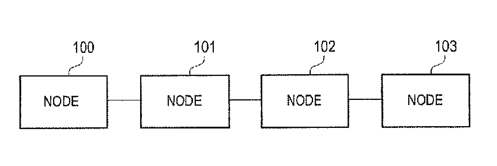
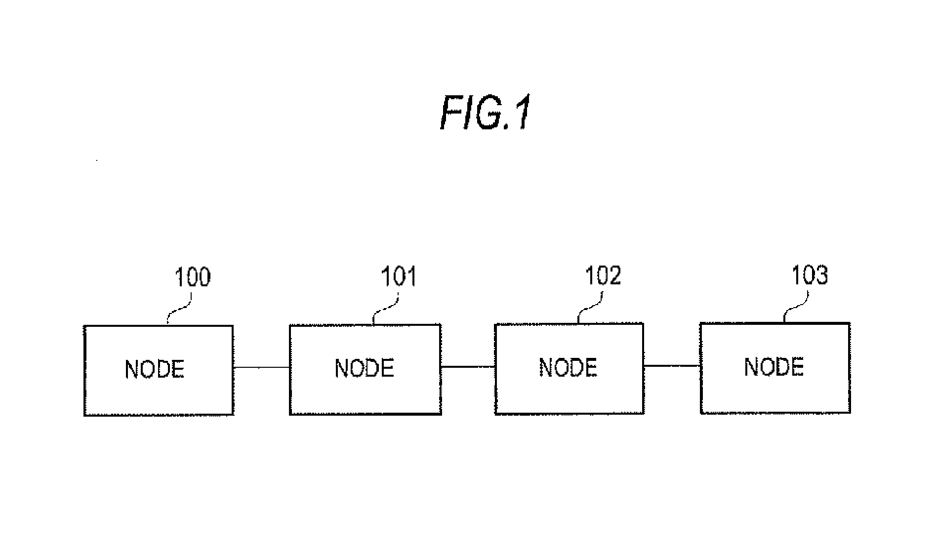
[0081]The entire configuration of the present exemplary embodiment will be described with reference to FIG. 1. Referring to FIG. 1, the present exemplary e...

second exemplary embodiment

[0154]In the above-mentioned first exemplary embodiment, the end-to-end one-way delay between the transmission source and destination nodes is measured by implementing the delay measurement section only in the transmission source and destination nodes. In the second exemplary embodiment, a one-way delay between an arbitrary pair of nodes located between the transmission source and destination nodes is measured. This allows a delay generated for each zone to be grasped. Thus, in a case where delay degradation has occurred end-to-end, a bottle-neck zone can be specified, allowing finer Performance Monitoring.

[0155]As in the first exemplary embodiment, in a situation where time synchronization is not achieved between the nodes to be measured in terms of delay, the one-way delay time of the DM packet forwarded in a direction from the transmission source node to the transmission destination node is measured.

[0156]

[0157]Hereinafter, descriptions of the same constituent elements as those o...


PUM


Abstract

The present invention measures 1-way delay without equipping all nodes with special functionality in a situation in which time has not been synchronized. The delay measurement system of the present invention has a transmission origin node and a transmission destination node which is connected to the transmission origin node through a network including relay nodes, and measures the delay time from the transmission origin node to the transmission destination node direction, wherein the transmission origin node generates a clock. On the basis of the generated clock, delay measurement packets are generated at regular periods. The generated delay measurement packets are transmitted to the transmission destination node. The transmission destination node selects the delay measurement packets from among the received frames. The delay received by the delay measurement packets in the network between the transmission origin node to the node itself is measured.

Description

TECHNICAL FIELD[0001]The present invention relates to end-to-end or zone-by-zone measurement of delay added when a packet forwarded in a network passes through a relay unit.BACKGROUND ART[0002]Along with recent adoption of IP / Ethernet® technology in user traffic, packetization of a carrier network is underway in order to efficiently accommodate packet traffic. A SONET / SDH-based network has used a carrier-class fine monitoring / control (OAM: Operations, Administration and Maintenance) function to respond to a carrier-grade service request. The SONET / SDH is a general term for SONET (Synchronous Optical NETwork) and SDH (Synchronous Digital Hierarchy). Hereinafter, “network” is often referred to as “NW”.[0003]Under a circumstance where a SONET / SDH carrier NW is shifted to a packet NW, the packet NW is required to realize an equivalent level of the OAM function to that of the carrier NW, and vigorous discussion is underway toward standardization.[0004]For example, the OAM for Ethernet® i...

Claims


Application Information

Patent Timeline
IPC IPC(8): H04L12/26H04L47/32
CPCH04L47/28H04L43/0852H04L47/32
Inventor UMAYABASHI, MASAKICUI, ZHENLONGTAKAGI, KAZUO
Owner NEC CORP
Why Eureka
Try Eureka