
Adaptable shoulder prosthesis cup

a shoulder and prosthesis technology, applied in the field of shoulder prosthesis cups, can solve the problems of reducing bone capital, requiring a long learning period, and requiring the use of ancillary that are often complex, and achieve the effect of improving the penetration of anchoring and/or coupling means, increasing the anchoring of the cup in the bone, and improving the penetration of the anchoring and/or coupling

Inactive Publication Date: 2013-07-04
DUPORT
View PDF2 Cites 22 Cited by
  • Summary
  • Abstract
  • Description
  • Claims
  • Application Information

AI Technical Summary

Benefits of technology

The present invention proposes an adaptable cup that can be used with different techniques while preserving the patient's bone capital. The cup can be easily and quickly placed. The design of the cup includes anchoring ribs that improve the penetration of the bone while fastening the cup, and prevent the cup from rotating and being pulled out after implantation. The technical effects of the invention are improved bone preservation and stability, as well as easier and safer placement of the cup.

Problems solved by technology

In this context, prosthetic shoulder surgery remains a very specialized, highly technical surgery, requiring a long learning period and the use of ancillaries that are often complex.
The installation of a humeral rod requires a significant recess in the bone to receive it, thereby decreasing the bone capital and making the bone more fragile.
The placement of such a prosthesis is long and complex.
With time, the cement may become dislocated and no longer ensure correct fixing of the rod.
However, the nature of the coupling of the cup and the anchoring pin does not make it possible to avoid rotation of the cup after it is implanted, which can cause problems.
Furthermore, the cup simply being interlocked in the cavity of the anchoring pin, the anchoring of the cup on the humeral head may prove insufficient, and thereby cause pain or discomfort for the patient.
Furthermore, if, the surgeon encounters difficulties during an operation, it is not possible for him to adapt the prosthesis, for example by changing the implantation method of the cup.

Method used


Image

  • Adaptable shoulder prosthesis cup
  • Adaptable shoulder prosthesis cup
  • Adaptable shoulder prosthesis cup

Examples


Embodiment Construction

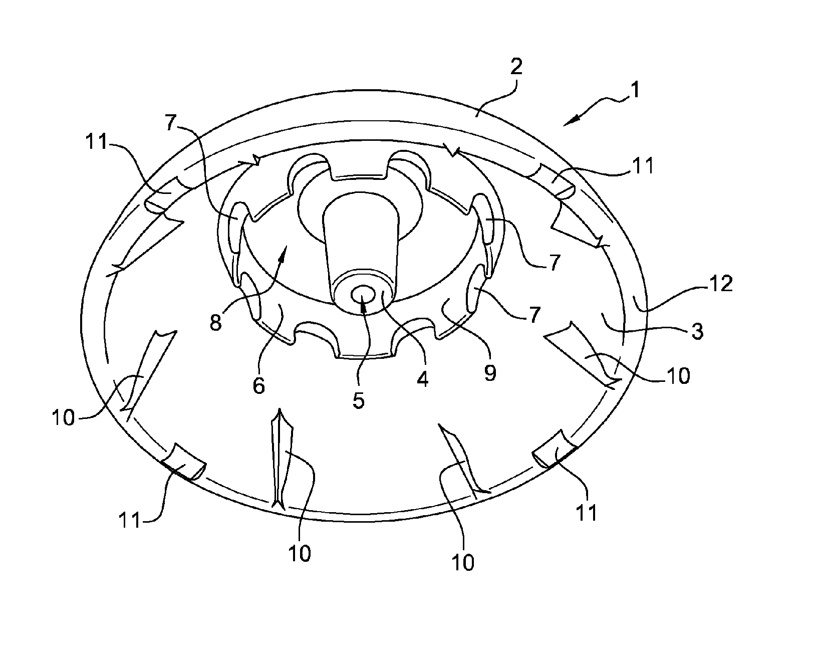
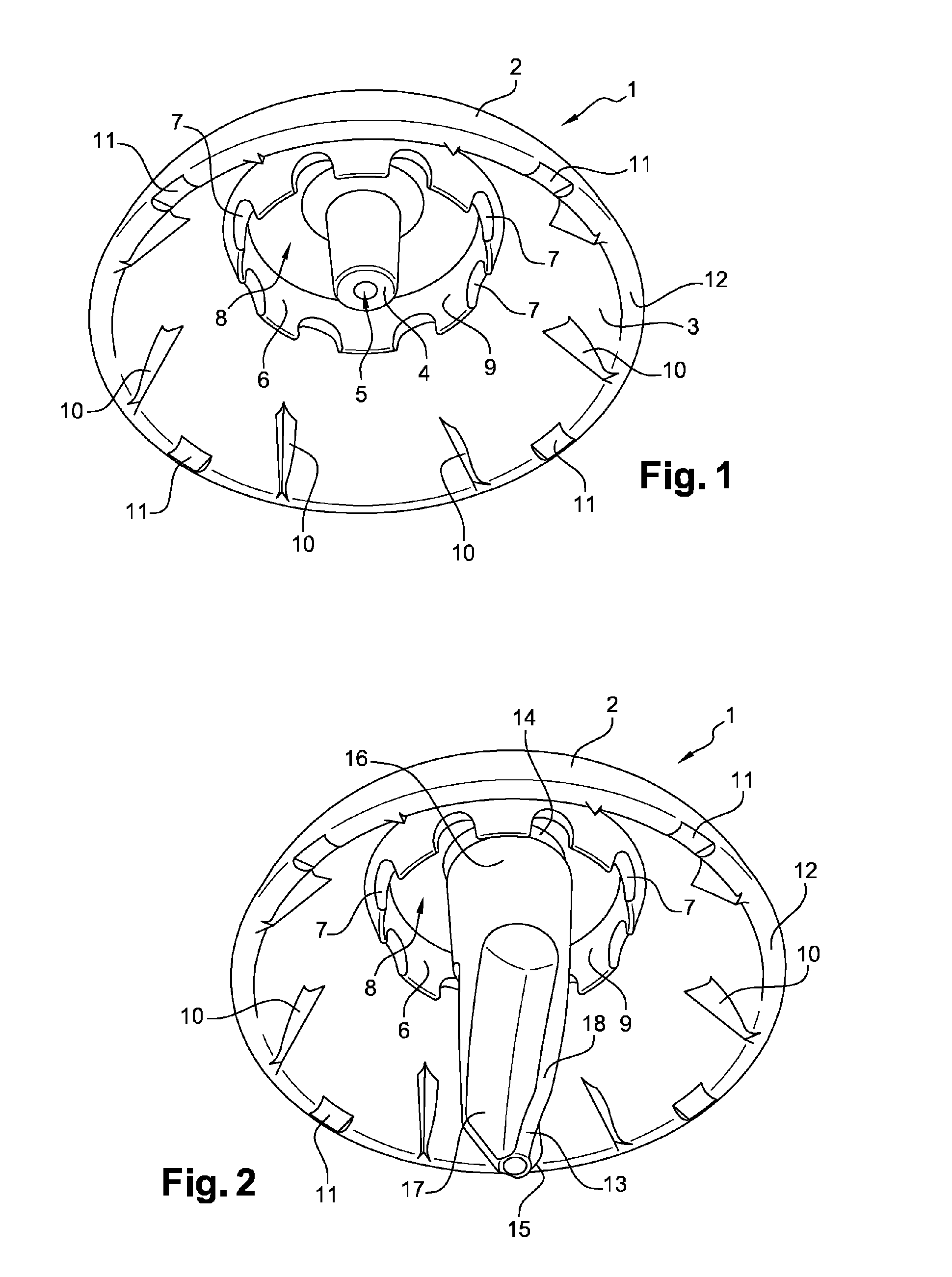
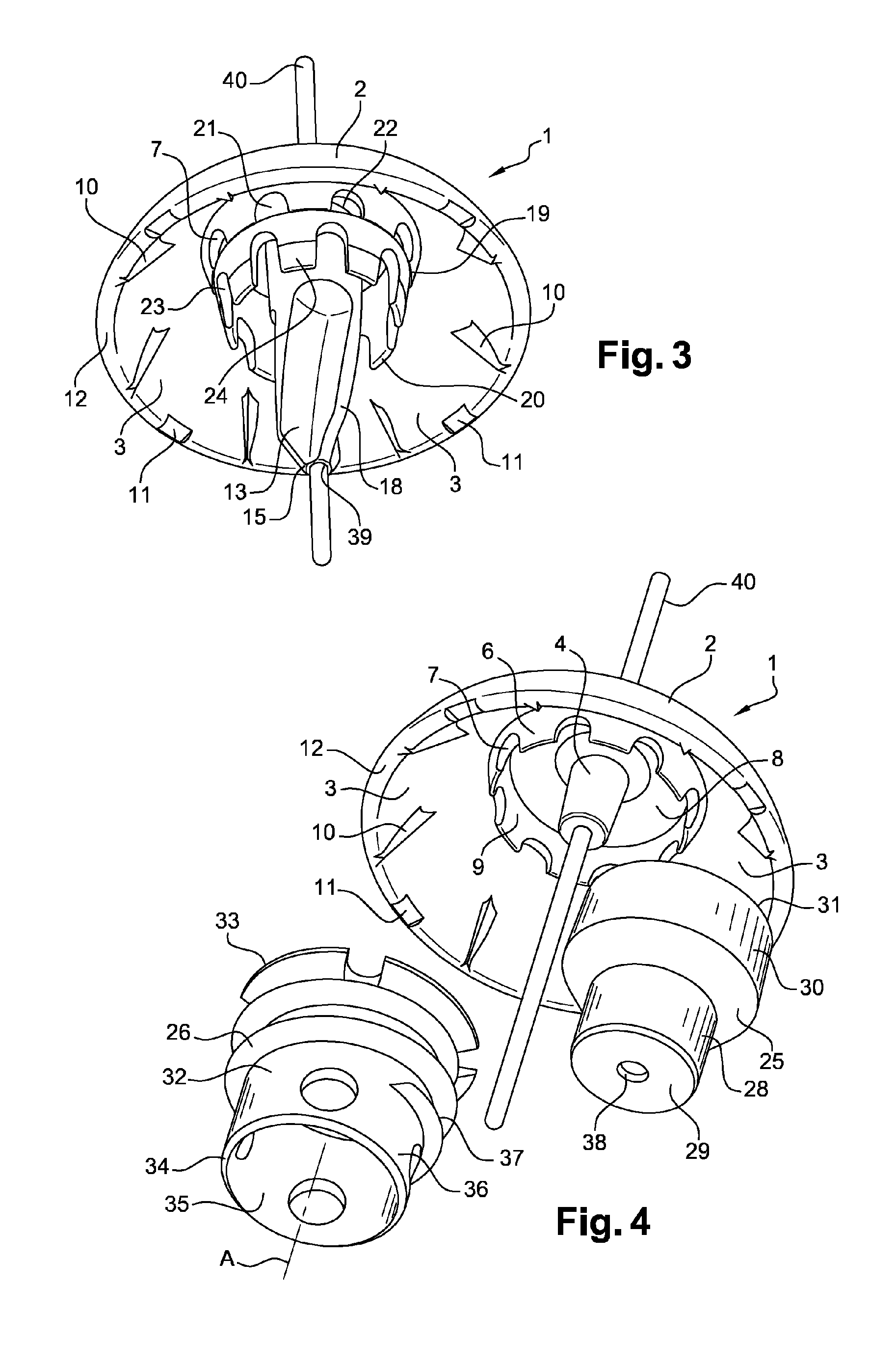
[0031]A prosthesis cup 1, illustrated in FIG. 1, includes a shell 2 substantially in the form of a hollow spherical cap. The shell 2 delimits a concave inner surface 3 and has a coupling stem 4 that extends from that inner surface 3 at the pole of the shell 2. The coupling stem 4 is, for example, provided with a through opening 5 extending along the axis of the spherical cap. The cup 1 also includes anchoring and / or coupling means such as a wall 6 that extends from the inner surface 3 and has a substantially tubular shape. This wall 6 includes eight gaps 7 formed at the free end thereof. Of course, the number of gaps 7 can be adapted as needed or depending on the size of the cup 2. Likewise, the shape of each gap 7 is adaptable and can, for example, be rounded, as illustrated in FIG. 1, or rectangular. Of course, the depth of each gap 7 may vary until it is substantially equal to the height of the wall 6. The thickness of the wall 6 decreases as it moves away from the inner surface ...


PUM


Abstract

The present invention relates to a prosthesis cup (1), particularly a shoulder prosthesis cup, comprising a shell (2) shaped substantially as a hollow spherical cap delimiting a concave inner surface (3), the shell (2) having a coupling stem (4) that extends from this inner surface (3) and is designed to permit coupling of the cup (1) to a fixing element, particularly an anchoring screw (26) or an anchoring pin (13), the cup (1) being characterized in that it additionally comprises anchoring and / or coupling means with a wall (6) which extends from the inner surface (3) of the shell (2) and has a substantially tubular shape and which, together with the coupling stem (4), delimits a recess (8) having what is substantially a ring shape.

Description

TECHNICAL FIELD[0001]The invention relates to a shoulder cup, in particular a shoulder prosthesis cup.RELATED ART[0002]In France, approximately 15,000 shoulder prostheses are placed each year, including total shoulder prostheses, called standard prostheses, reverse prostheses, and more recently resurfacing prostheses.[0003]This figure, which shows a clear increase in recent years, is in particular due to the increase in the number of pathologies for which the placement of a shoulder prosthesis is now indicated.[0004]In this context, prosthetic shoulder surgery remains a very specialized, highly technical surgery, requiring a long learning period and the use of ancillaries that are often complex. It is therefore desirable to simplify the prostheses and ancillaries so as to facilitate the procedures, make it more reproducible, and therefore decrease postoperative complications. Such a simplification of the ancillary and the procedure may also have the advantage of decreasing the costs...

Claims


Application Information

Patent Timeline
IPC IPC(8): A61F2/40
CPCA61F2/4003A61F2/4014A61F2002/30235A61F2002/30607A61F2002/30772A61F2002/30818A61F2/4081A61F2002/3085A61F2002/30878A61F2002/30884A61F2002/4007A61F2002/4025A61F2002/30845A61F2002/30593
Inventor DUPORT, MARC
Owner DUPORT
Learn More