
Method and system for controlling lifting operation of wearable robot

Active Publication Date: 2013-07-04
HYUNDAI MOTOR CO LTD
View PDF3 Cites 20 Cited by
  • Summary
  • Abstract
  • Description
  • Claims
  • Application Information

AI Technical Summary

Benefits of technology

The present invention aims to solve the problems in the prior art by providing a method and system for controlling the lifting operation of a wearable robot. This system can incorporate the user's intention in the form of a force at the end of the robot, allowing it to operate in compliance with the user's intention and provide a constant force to the user. This results in a more intuitive and comfortable experience for the user.

Problems solved by technology

However, such a robot is disadvantageous in that when the wearing user moves, a phenomenon frequently occurs in which the EMG sensor is not closely attached in an exact location to the body of the user, with the result that the motion intention signal of the wearing user is distorted.
Further, the robot is disadvantageous in that the operation of the robot reacts sensitively to a variation in the weight of an object to be lifted.
An attachment-type EMG sensor is considerably inaccurate in a certain aspect and is expensive, thereby making it difficult to commercialize.

Method used


Image

  • Method and system for controlling lifting operation of wearable robot
  • Method and system for controlling lifting operation of wearable robot
  • Method and system for controlling lifting operation of wearable robot

Examples


Embodiment Construction

[0023]Hereinafter, embodiments of a method and system for controlling the lifting operation of a wearable robot according to the present invention will be described in detail with reference to the attached drawings.

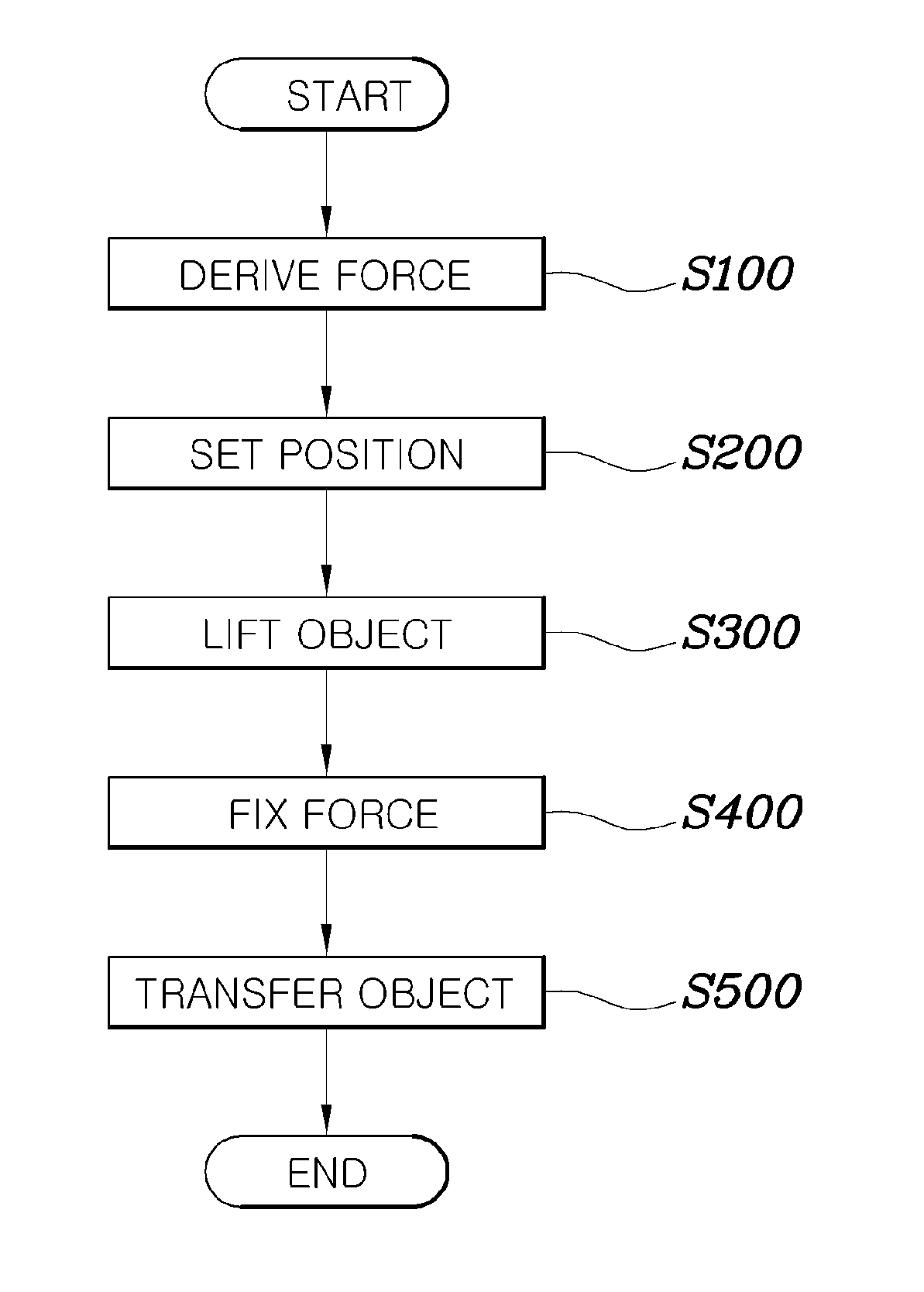
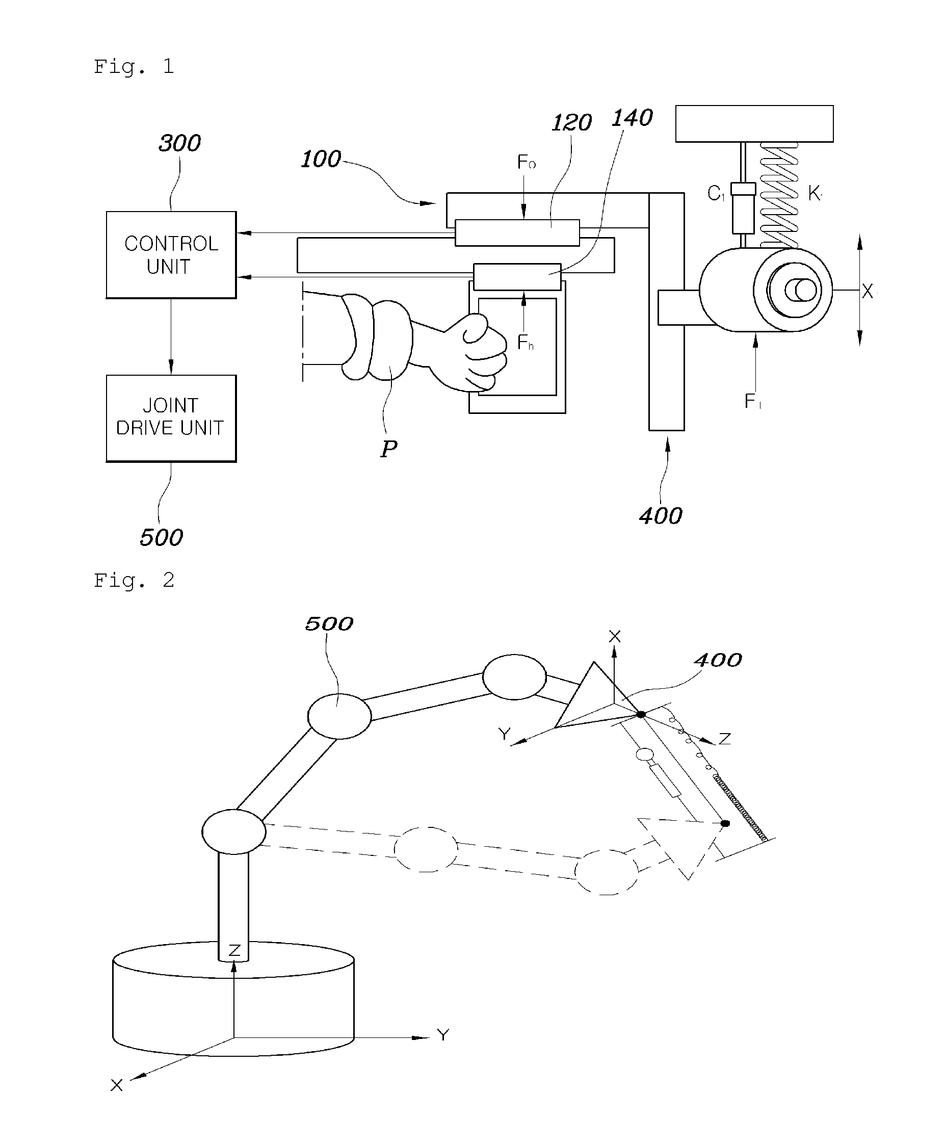
[0024]FIG. 1 is a diagram showing a system for controlling the lifting operation of a wearable robot according to an embodiment of the present invention, FIG. 2 is a diagram showing the control of the driving unit of the wearable robot of FIG. 1, and FIG. 5 is a flowchart showing a method of controlling the lifting operation of the wearable robot according to an embodiment of the present invention.

[0025]Referring to FIG. 5, a method of controlling the lifting operation of the wearable robot according to the present invention includes a force derivation step S100, a position setting step S200, a lifting step S300, and a fixing step S400. In step S100, a final force FT that must be applied by the robot to an object upon conducting a lifting operation is derived on the basis...


PUM


Abstract

Disclosed herein is a method and system for controlling the lifting operation of a wearable robot. A final force that must be applied by the robot to an object upon conducting a lifting operation is derived based on a difference between a weight force applied by the object to the robot and an apply force applied by a wearing user to the robot. A target position to which the robot lifts the object is set. A spring-damper virtual force model is applied to an end of the robot and to joints of the robot, the final force is converted into final torques required by the joints of the robot by being incorporated into the virtual force model, and then the joints of the robot are operated based on the final torques. The final force is fixed once the robot has lifted the object to the target position.

Description

CROSS-REFERENCE TO RELATED APPLICATIONS[0001]The present application claims priority to Korean Patent Application No. 10-2012-0000025 filed on Jan. 2, 2012, the entire contents of which is incorporated herein for purposes by this reference.FIELD OF THE INVENTION[0002]The present invention relates to a method and system for controlling the lifting operation of a wearable robot, which can perform control so that a wearing user can always lift objects having various weights with a constant force regardless of a variation in the weight of an object to be lifted.BACKGROUND OF THE INVENTION[0003]A wearable muscular power assist robot must lift and transfer an object while moving depending on a wearing user's intention. When the robot lifts a heavy object, the force of the wearing user is transferred to the robot, and the force transferred to the robot is amplified, thus enabling the robot to lift the heavy object. The present invention relates to a method of performing control so that a w...

Claims


Application Information

Patent Timeline
IPC IPC(8): G05B15/00
CPCG05B15/00B25J9/0006G05B2219/37357G05B2219/39523G05B2219/40305B25J13/085B25J9/16B25J9/06
Inventor SEO, JUNG HOYANG, WOO SUNG
Owner HYUNDAI MOTOR CO LTD
Learn More