Vehicle travel control device

a technology of vehicle travel control and control device, which is applied in the direction of automatic initiation, transportation and packaging, instruments, etc., can solve the problems of increasing the reaction force applied to the accelerator pedal, the driver may feel uncomfortable concerning the vehicle speed, and the speed difference between the present speed and the recommended speed becomes so large, so as to prevent the effect of preventing the driver from feeling ill at eas

Active Publication Date: 2013-07-04
HONDA MOTOR CO LTD
View PDF13 Cites 32 Cited by
  • Summary
  • Abstract
  • Description
  • Claims
  • Application Information

AI Technical Summary

Benefits of technology

[0009]If the navigation system in a vehicle detects a curved road ahead, or if the intervehicular distance sensor on the vehicle detects a decreasing distance to a leading vehicle while the vehicle is traveling, then according to the technique disclosed in JP2009-262846A, a recommended speed is established as an extremely low speed. Therefore, the speed difference between the present speed and the recommended speed becomes so large that the reaction force applied to the accelerator pedal increases quickly.

Problems solved by technology

Therefore, the speed difference between the present speed and the recommended speed becomes so large that the reaction force applied to the accelerator pedal increases quickly.
The driver may thus possibly feel uncomfortable concerning the vehicle speed.
However, the approaching speed may possibly become inappropriate on account of errors that occur when the navigation system detects the present position of the vehicle, or due to inaccuracies in the map information stored in the navigation system.
If the approaching speed is inappropriate, then a warning or an automatic brake may not necessarily be triggered in a manner that is suitable for the driver, thereby tending to make the driver feel ill at ease.
According to JP2007-022238A, since the accuracy of the range-finding radar may possibly vary depending on the external situation, a warning or an automatic brake may not necessarily be triggered in a manner that is suitable for the driver, thereby tending to make the driver feel ill at ease.

Method used


Image

  • Vehicle travel control device
  • Vehicle travel control device
  • Vehicle travel control device

Examples


first embodiment

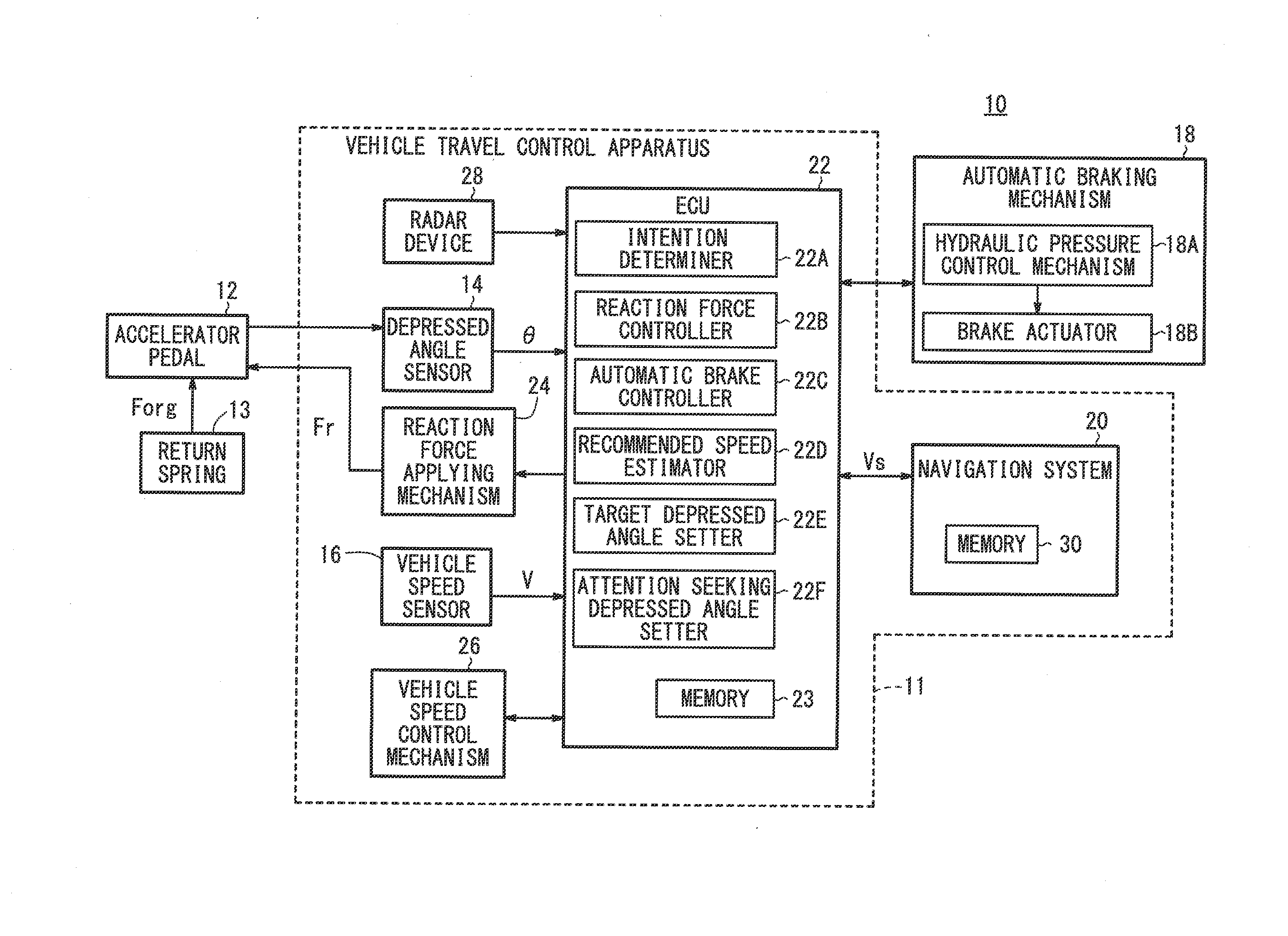
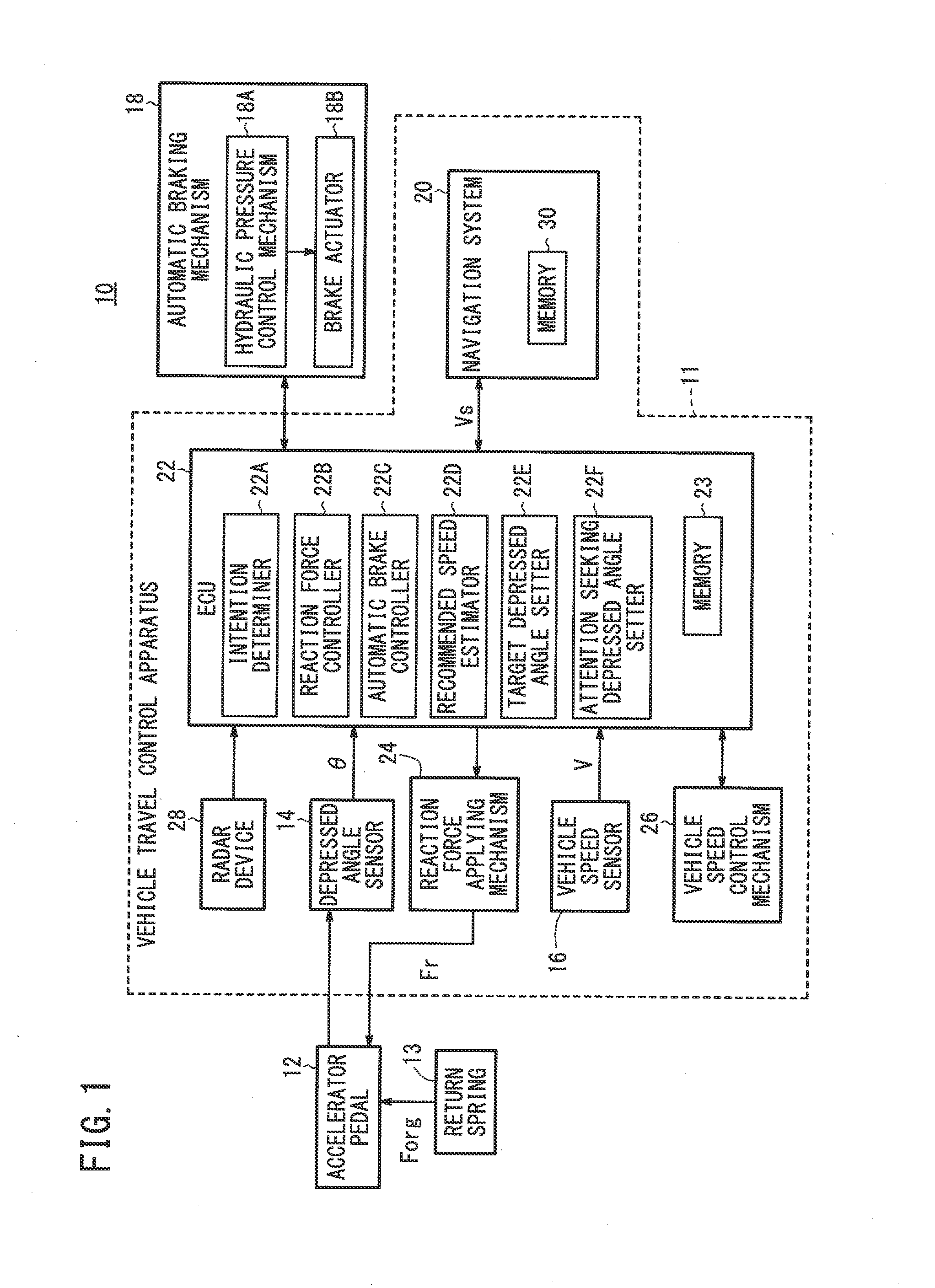
[0071]FIG. 1 is a block diagram of a vehicle 10 incorporating therein a vehicle travel control apparatus 11 according to a first embodiment of the present invention. The vehicle 10 includes an accelerator pedal 12, a return spring 13 for applying a reaction force Forg (also referred to as an “original position returning force Forg”) [N] as an original position returning force to the accelerator pedal 12, a depressed angle sensor 14 (accelerator pedal depressed angle sensor), a vehicle speed sensor 16 (speedometer), an automatic braking mechanism 18, a navigation system 20, an ECU (electronic control unit) 22, a reaction force applying mechanism 24, a vehicle speed control mechanism 26, and a radar device 28. Among these components, the depressed angle sensor 14, the vehicle speed sensor 16, the radar device 28, the navigation system 20, the ECU 22, the vehicle speed control mechanism 26, and the reaction force applying mechanism 24 jointly make up the vehicle travel control apparatu...

second embodiment

1. Arrangement of Vehicle 10

[0139]FIG. 7 is a block diagram of a vehicle 10, which incorporates therein a vehicle travel control apparatus 11 according to a second embodiment of the present invention. The vehicle 10 includes an accelerator pedal 12, a return spring 13 for applying a reaction force Forg to the accelerator pedal 12, a depressed angle sensor 14, a vehicle speed sensor 16, a radar device 28, an automatic cruising switch 29, a navigation system 20, an electronic control unit (ECU) 22, a reaction force applying mechanism 24, which comprises an actuator, and an automatic braking mechanism 18. Among these components, the depressed angle sensor 14, the vehicle speed sensor 16, the radar device 28, the automatic cruising switch 29, the navigation system 20, the ECU 22, and the reaction force applying mechanism 24 jointly make up the vehicle travel control apparatus 11.

[0140]The accelerator pedal depressed angle sensor 14 detects a depressed angle (hereinafter referred to as a...


PUM


Abstract

A vehicle travel control device can accurately determine a driver's intention to adjust the vehicle speed. After applying attention attracting reaction force corresponding to outside circumstances and the like to an accelerator pedal through a reaction force application mechanism, a reaction force control unit outputs intention determining reaction force that is used to determine the driver's intention to adjust the vehicle speed and is smaller than the attention attracting reaction force, and determines the intention to adjust the vehicle speed on the basis of the accelerator pedal operation amount of the driver while the intention determining reaction force is being applied to the accelerator pedal through the reaction force application mechanism.

Description

TECHNICAL FIELD[0001]The present invention relates to a vehicle travel control apparatus (device) for determining the intention of a driver to adjust the vehicle speed of a vehicle (host vehicle) based on the depression of an accelerator pedal, which is caused by the driver with respect to a reaction force applied to the accelerator pedal from the vehicle while the vehicle is traveling, and for controlling the reaction force applied to the accelerator pedal based on a recommended speed, which is established depending on an external situation around the vehicle, or depending on information representing the traveling state of the vehicle.BACKGROUND ART[0002]Heretofore, there has been proposed a vehicle travel control apparatus for determining the intention of a driver to adjust the vehicle speed of a vehicle based on the depression of an accelerator pedal, which is caused by the driver against a reaction force applied to the accelerator pedal. See, Japanese Laid-Open Patent Publicatio...

Claims


Application Information

Patent Timeline
Patent Type & Authority Applications(United States)
IPC IPC(8): B60Q9/00B60T7/22
CPCB60K26/021B60W50/10B60W10/06B60W10/184B60W30/143B60W30/18145B60W50/087B60W50/14B60W2520/10B60W2540/10B60W2550/146B60Q9/008B60W50/16B60K26/02B60K2026/023B60W2540/106B60T7/22B60W2552/30
Inventor TAKIGUCHI, HIROTAKASUZAKI, GOSUGIMOTO, YOICHI
Owner HONDA MOTOR CO LTD
Why Eureka
Try Eureka