Microwave oven with antenna array

a microwave oven and antenna array technology, applied in microwave heating, electrical/magnetic/electromagnetic heating, electrical apparatus, etc., can solve the problems of large power consumption and large magneton size, and achieve the effect of reducing the weight and dimensions of the oven, consuming less power, and being more effective at heating items

Inactive Publication Date: 2013-07-11
GHARPUREY RANJIT +1
View PDF5 Cites 22 Cited by
  • Summary
  • Abstract
  • Description
  • Claims
  • Application Information

AI Technical Summary

Benefits of technology

[0009]In some instances, the microwave oven described herein may be more effective at heating items while also consuming less power than prior microwave ovens.
[0010]In some embodiments it may be possible to reduce the weight and dimensions of the oven

Problems solved by technology

Magnetrons can be rather large and consume large amounts of power.

Method used


Image

  • Microwave oven with antenna array
  • Microwave oven with antenna array
  • Microwave oven with antenna array

Examples


Embodiment Construction

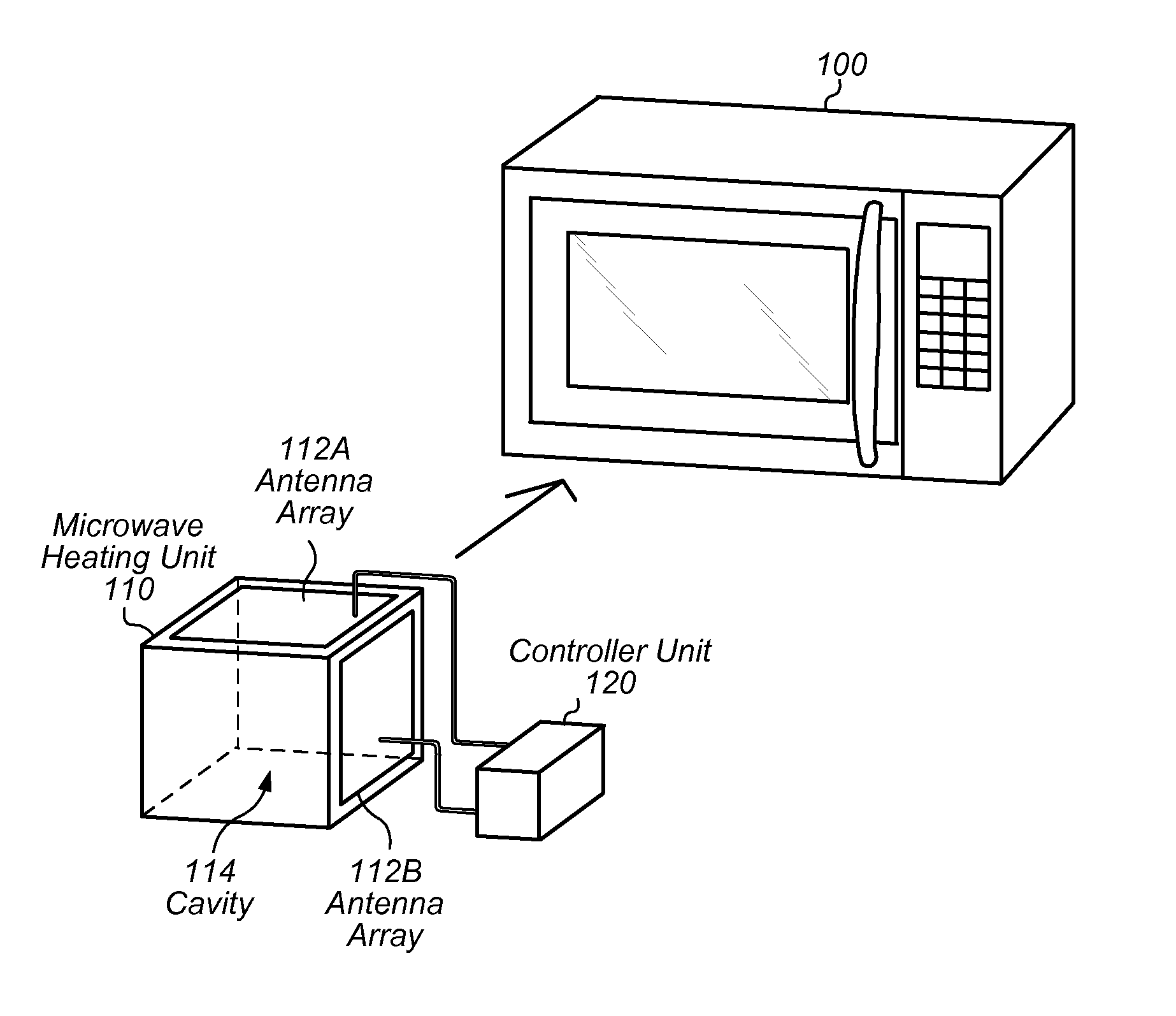
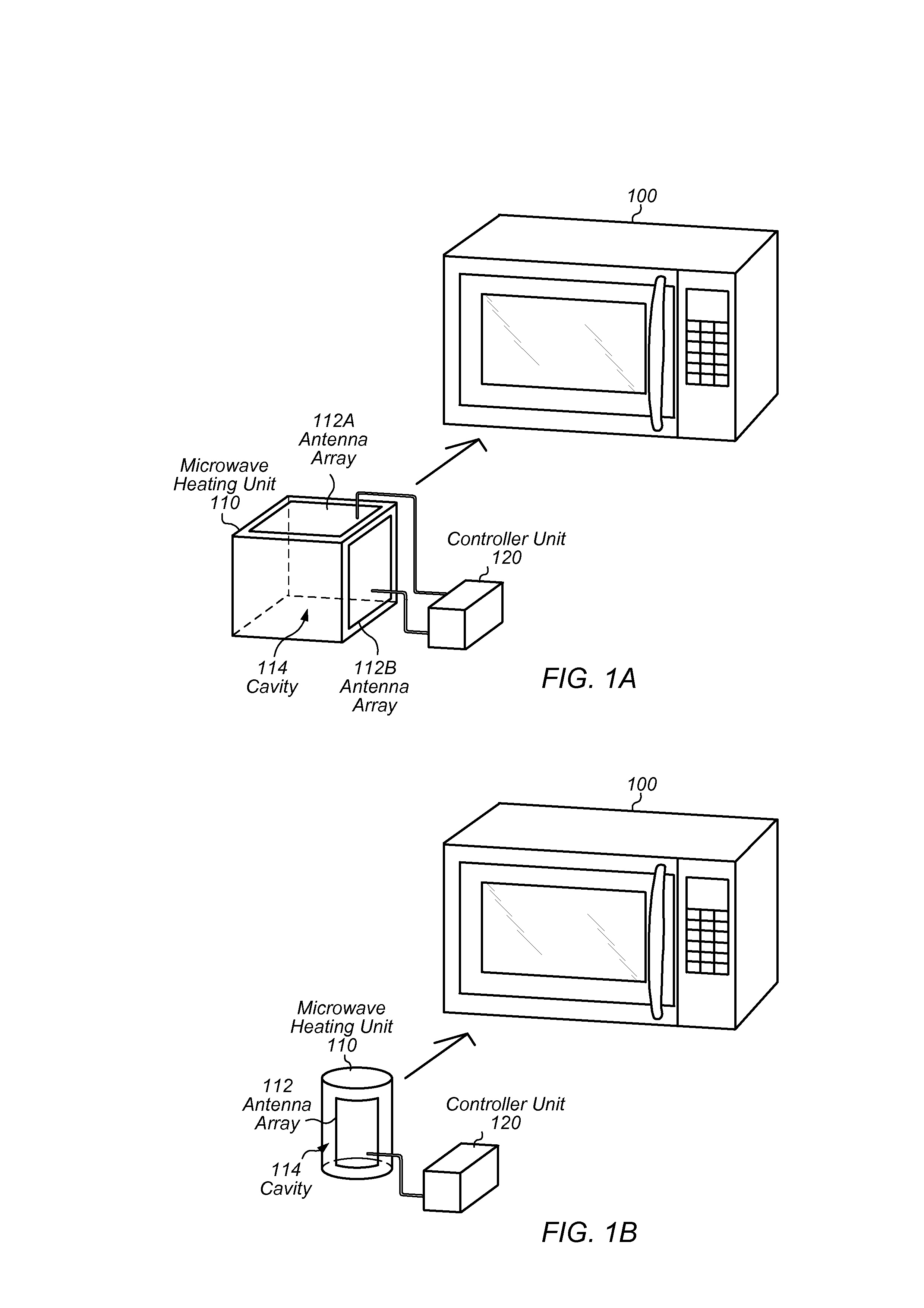
[0019]Turning now to FIG. 1A, a block diagram of a microwave oven 100 is depicted. As will be described below, microwave oven 100 is one embodiment of a microwave oven that is configured to heat items using an antenna array. In the illustrated embodiment, microwave oven 100 includes a microwave heating unit 110 and a controller unit 120.

[0020]Microwave heating unit 110, in one embodiment, is configured to radiate microwaves into a cavity 114 by using one or more antenna arrays 112. In the illustrated embodiment, microwave heating unit 110 has a cuboidal structure (i.e., a “rectangular-box” structure) that defines a cuboidal cavity 114 for storing items being heated. Heating unit 110 includes a first antenna array 112A positioned along a first surface of cavity 114 and a second antenna array 112B positioned along a second surface of cavity 114. In some embodiments, heating unit 110 may include more or less antenna arrays 112 than shown; in some embodiments, multiple arrays 112 may be...


PUM


Abstract

Techniques are disclosed relating to microwave ovens. In one embodiment, an apparatus is disclosed that includes a microwave heating unit. The microwave heating unit is configured to radiate microwaves into a cavity and includes an antenna array coupled to one or more amplifiers. The antenna array is configured to generate the radiated microwaves. In some embodiments, the microwave oven is configured to measure temperatures of a item within the cavity, and to steer a microwave beam produced by the antenna array based on the measured temperatures.

Description

[0001]The present application claims priority to U.S. Provisional Appl. No. 61 / 583,912, filed Jan. 6, 2012; the disclosure of which is incorporated by reference herein in its entirety.BACKGROUND[0002]1. Technical Field[0003]This disclosure relates generally to appliances, and, more specifically, to microwave ovens.[0004]2. Description of the Related Art[0005]Microwave ovens cook food by radiating microwaves through a cavity to perform dielectric heating. Microwave ovens have traditionally generated microwaves with a magnetron, which converts high-voltage energy to microwave radiation. Magnetrons can be rather large and consume large amounts of power. Magnetrons also tend to have a wide frequency variance, rather than consistently generating microwaves at a specific frequency such as 2.45 GHz, which is a suitable for microwave ovens.SUMMARY[0006]The present disclosure describes embodiments of structures and techniques that may be used by a microwave oven.[0007]In one embodiment, a mi...

Claims


Application Information

Patent Timeline
Patent Type & Authority Applications(United States)
IPC IPC(8): H05B6/72
CPCH05B6/70H05B6/72
Inventor GHARPUREY, RANJITABRAHAM, JACOB A.
Owner GHARPUREY RANJIT
Why Eureka
Try Eureka