Quick-connect coupler

a technology of coupling and coupling, applied in the direction of couplings, pipe elements, branching pipes, etc., can solve the problem of expulsion outside the receiving portion, and achieve the effect of limiting the growth of bacteria in the fluid and ensuring the hygien

Inactive Publication Date: 2013-07-18
COMAP
View PDF2 Cites 29 Cited by
  • Summary
  • Abstract
  • Description
  • Claims
  • Application Information

AI Technical Summary

Benefits of technology

[0020]Such an arrangement allows the user to view the engagement of the tube in the receiving portion, while protecting the fluid from the light rays.
[0021]Such an arrangement makes it possible to limit bacterial growth of the fluid, and to subsequently guarantee the hygiene of the fluid. This coupling is then perfectly adapted to be used in a potable water distribution network.

Problems solved by technology

In the event the tube is insufficiently engaged, the flow of pressurized fluid inside that tube can lead to its expulsion outside the receiving portion.

Method used


Image

  • Quick-connect coupler
  • Quick-connect coupler
  • Quick-connect coupler

Examples


Embodiment Construction

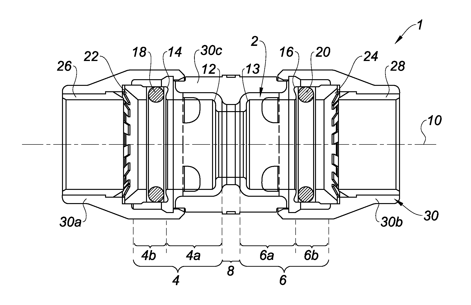
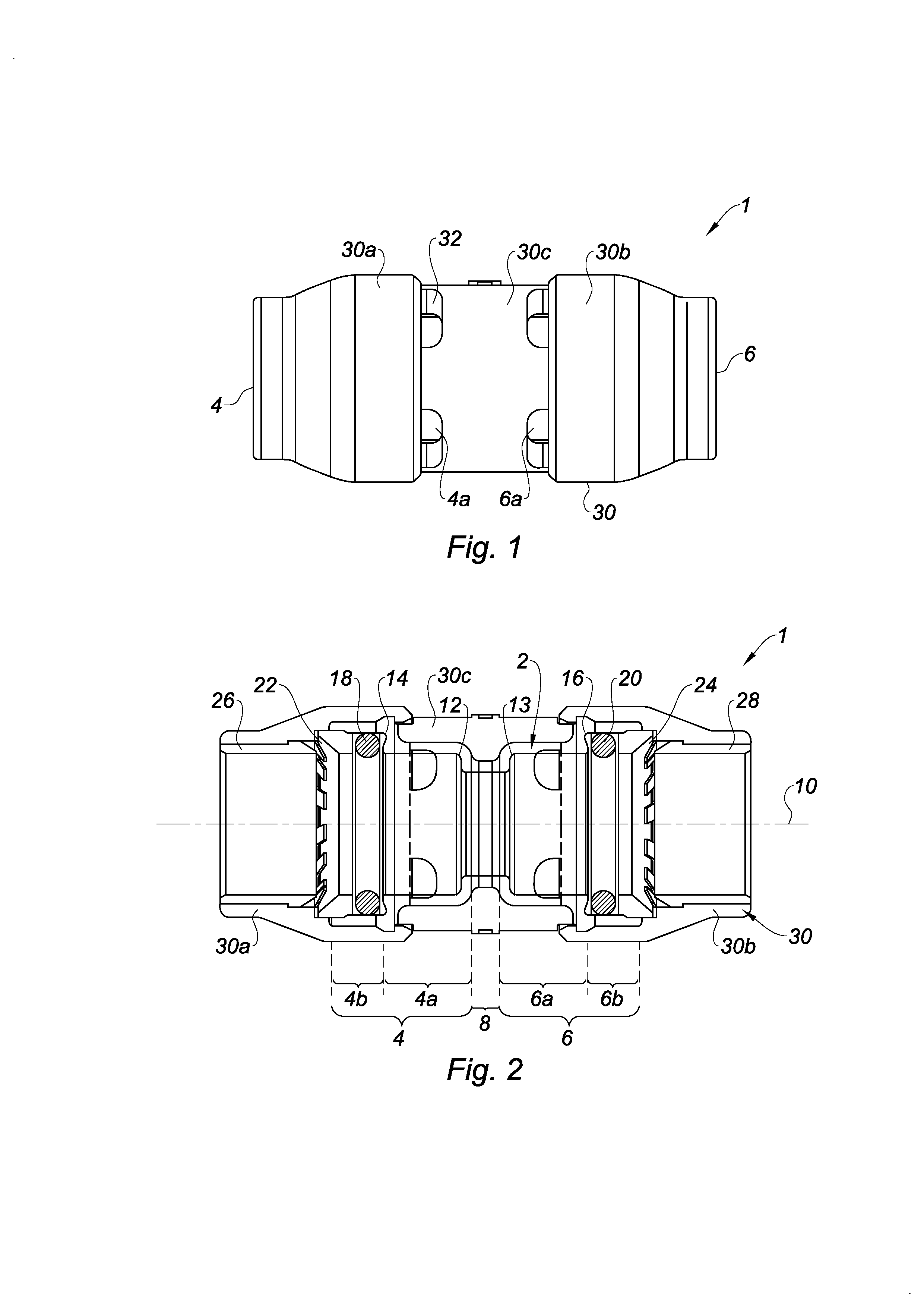
[0043]FIGS. 1 and 2 show a quick-connect coupling 1 for the fluid connection of two tubes of an irrigation network or a potable water distribution network.

[0044]The coupling 1 comprises a tubular body 2 made from a transparent plastic material. Here, the body 2 is made from clarified polypropylene. Alternatively, the body 2 can be made from polyamide, polysulfone, polyphenylsulfone (PPSU), or others.

[0045]The body 2 has two receiving portions 4 and 6 shaped to receive an end segment of the tube, and a connecting portion 8 connecting the receiving portions 4 and 6. The receiving portions 4 and 6 extend along a same axis 10. The receiving portions 4 and 6 respectively comprise parts 4a and 6a turned toward the connecting portion 8. The receiving portions 4 and 6 respectively comprise parts 4b and 6b opposite the parts 4a and 6a.

[0046]The inner diameter of the parts 4a and 6a is larger than the inner diameter of the connecting portion 8, forming shoulders 12 and 13. The inner diameter...


PUM


Abstract

The invention relates to a quick-connect coupler for at least one tube, including a tubular body having at least one receiving portion shaped to receive an end segment of the tube, the receiving portion being at least partially made from a transparent material, so as to make it possible to view the end segment of the tube when the latter is received in the receiving portion, and a retaining member mounted inside the receiving portion, arranged to oppose the withdrawal of the tube when a pulling force is exerted on the tube.

Description

TECHNICAL FIELD[0001]The present invention relates to a quick-connect coupling for at least one tube.BRIEF DISCUSSION OF RELATED ART[0002]Such a coupling is, for example, applicable for the fluid connection of the tube to a device, such as a tap or a collector, or for the fluid connection of tubes of an irrigation or potable water distribution network.[0003]A quick-connect coupling, known in the state of the art, comprises a tubular body having a receiving portion shaped to receive an end segment of the tube. The coupling comprises a ring, mounted inside the body, equipped with prongs. These prongs are arranged to oppose the withdrawal of the tube when a pulling force is exerted on said tube.[0004]In usage conditions, a user engages an end segment of a tube in the receiving portion. The user then has no means to judge the engaged length of the tube.[0005]In the event the tube is insufficiently engaged, the flow of pressurized fluid inside that tube can lead to its expulsion outside ...

Claims


Application Information

Patent Timeline
Patent Type & Authority Applications(United States)
IPC IPC(8): F16L21/06
CPCF16L41/021F16L43/00F16L2201/10F16L37/0915
Inventor LE CLINCHE, PASCAL
Owner COMAP
Why Eureka
Try Eureka