Battery pack and liquid leakage detection method thereof

a battery box and liquid leakage detection technology, applied in the field of battery boxes, can solve the problems of reducing the safety of the battery pack, endangering the vehicle, and affecting so as to avoid risks and improve the safety of the battery box

Active Publication Date: 2013-07-18
MICROVAST
View PDF0 Cites 26 Cited by
  • Summary
  • Abstract
  • Description
  • Claims
  • Application Information

AI Technical Summary

Benefits of technology

[0006]An objective of the present disclosure is to provide a safer battery pack and a liquid leakage detection method of a battery pack.
[0018]Preferably, a bottom surface of each of the battery cells is fixed to the cover plate so that the battery cells can be fixed more securely.
[0021]Preferably, a recess is formed at a V-shaped or U-shaped bottom of the collection portion. The V-shaped bottom formed with the recess or the U-shaped bottom formed with the recess can collect the leaked electrolyte more easily because the electrolyte falls and is converged into the recess under the action of the gravity.
[0025]Through the solutions of the present disclosure, the leaked electrolyte can be enclosed in the fire-retardant isolated liquid so that the electrolyte is prevented from contacting with the air and thus cannot be combusted even at a high temperature so as to avoid risks; detecting at the first time whether liquid leakage occurs to any of the battery cells in the battery box and sending an alert can improve the safety of the battery box; and immersing the electrical components into the isolated liquid can prevent the electrical components from contacting with the air to be aged or combusted.

Problems solved by technology

The batteries may be subject to liquid leakage after being used for a period of time due to defects or unreasonable installation and fixation structures of the batteries.
This will reduce the safety of the battery pack and endanger the vehicle.
If these gases are detected by the detector, it represents that an accident of leakage occurs to the battery pack.
However, this detection method has some shortcomings: 1. the gas detector is relatively expensive, and cannot deliver a good detection effect when the concentration of the gases is relatively low; and 2. the gas detector cannot work effectively until the gases in the battery box reach a certain concentration and, at this time, a relatively large amount of the electrolyte has been leaked.
Because the flammable electrolyte is exposed to the air, this make accidents of fires and combustion likely to occur.

Method used


Image

  • Battery pack and liquid leakage detection method thereof
  • Battery pack and liquid leakage detection method thereof
  • Battery pack and liquid leakage detection method thereof

Examples


embodiment 1

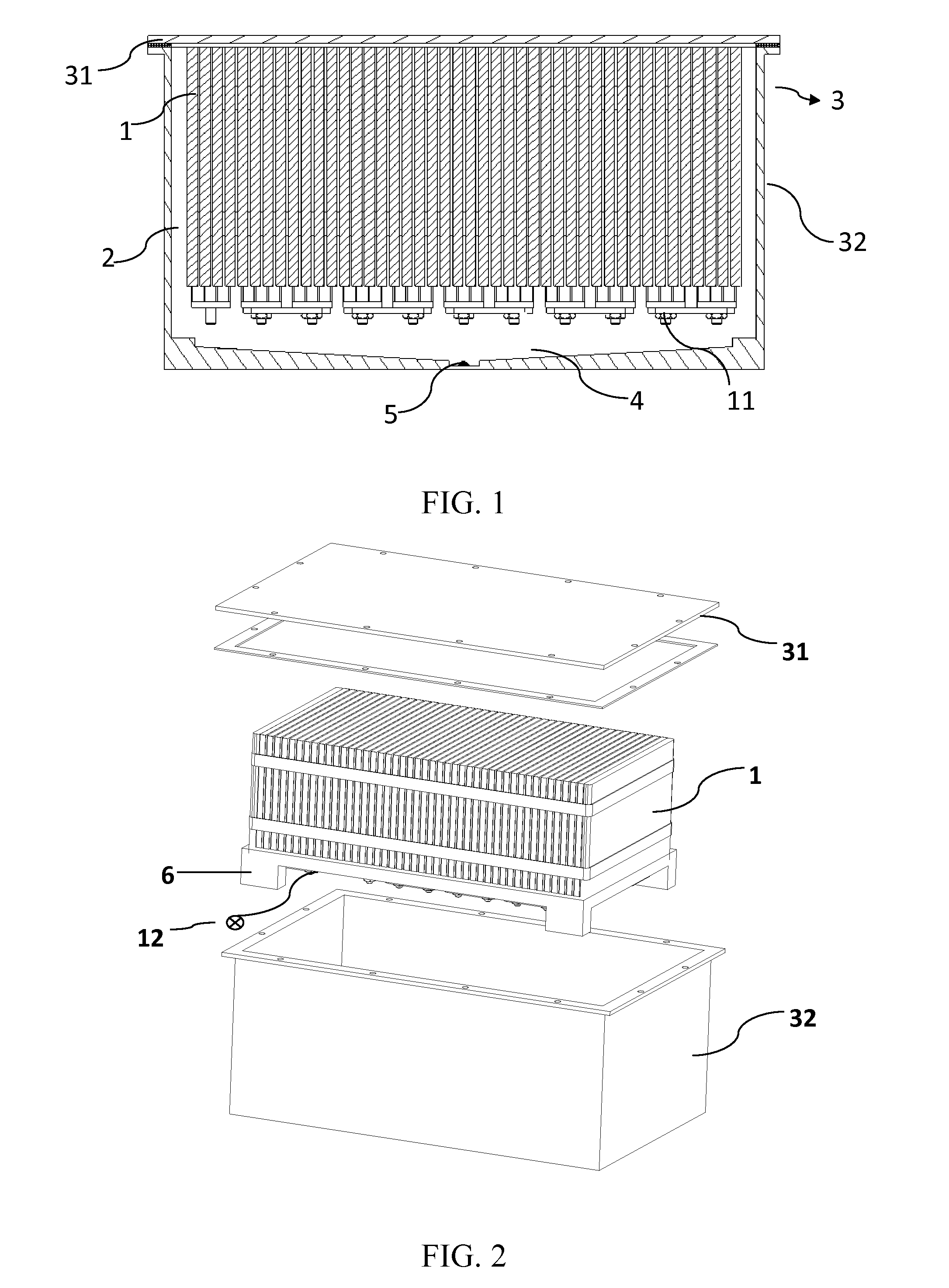
[0031]As shown in FIG. 1 and FIG. 3, a battery box 3 comprising a box body 32 and a cover plate 31, and a battery pack is soaked in a isolated liquid 2. The battery pack may be partially soaked in the isolated liquid 2 and may also be completely soaked in the isolated liquid 2; however, all of heating components and easy-to-leak components in the battery box must be merged in the isolated liquid 2. battery cells 1 are placed in the box body 32, and are connected in series or in parallel to form a battery module. The battery cells are placed upside down in the battery box 3 with a surface where electrodes of the battery cells 1 are located facing the bottom of the battery box 3; i.e., the battery cells 1 are disposed upside down. In this case, a bottom surface of each of the battery cells 1 is fixed to the cover plate 31. The battery cells 1 are partially or completely soaked in the isolated liquid 2, the battery cells 1 are placed upside down, and the “Placing the battery cells 1 up...

embodiment 2

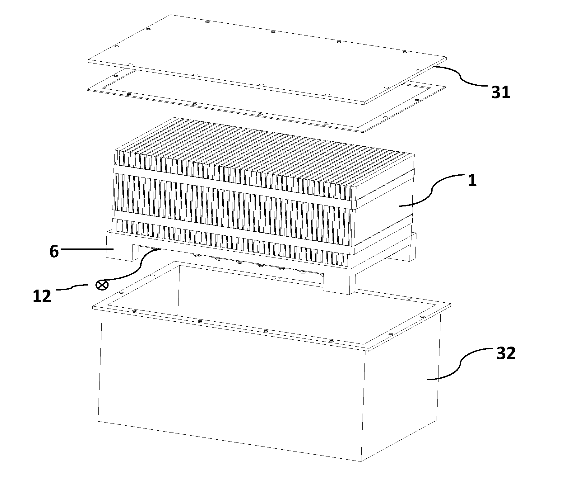
[0036]As shown in FIG. 3 and FIG. 4, a battery box 3 comprising a box body 32 and a cover plate 31, and a battery pack is soaked in a isolated liquid. battery cells 1 are placed in the box body 32, and are connected in series or in parallel to form a battery module. The battery cells are placed upside down in the battery box 3 with a surface where electrodes of the battery cells 1 are located facing the bottom of the battery box 3.

[0037]As shown in FIG. 2, a support frame 6 is disposed on the surface, where the electrodes 11 of the battery pack are located, to support the whole battery pack. A collection portion 4 at the bottom of the box body 32 is a U-shaped bottom of the box body that is in a funnel form. “Disposing a support frame at the bottom of the battery box 3 to support the battery cells 1 overhead” means supporting electrode tabs of the battery cells 1 overhead within the battery box 3 to prevent the electrode tabs from contacting with the bottom surface of the battery bo...

embodiment 3

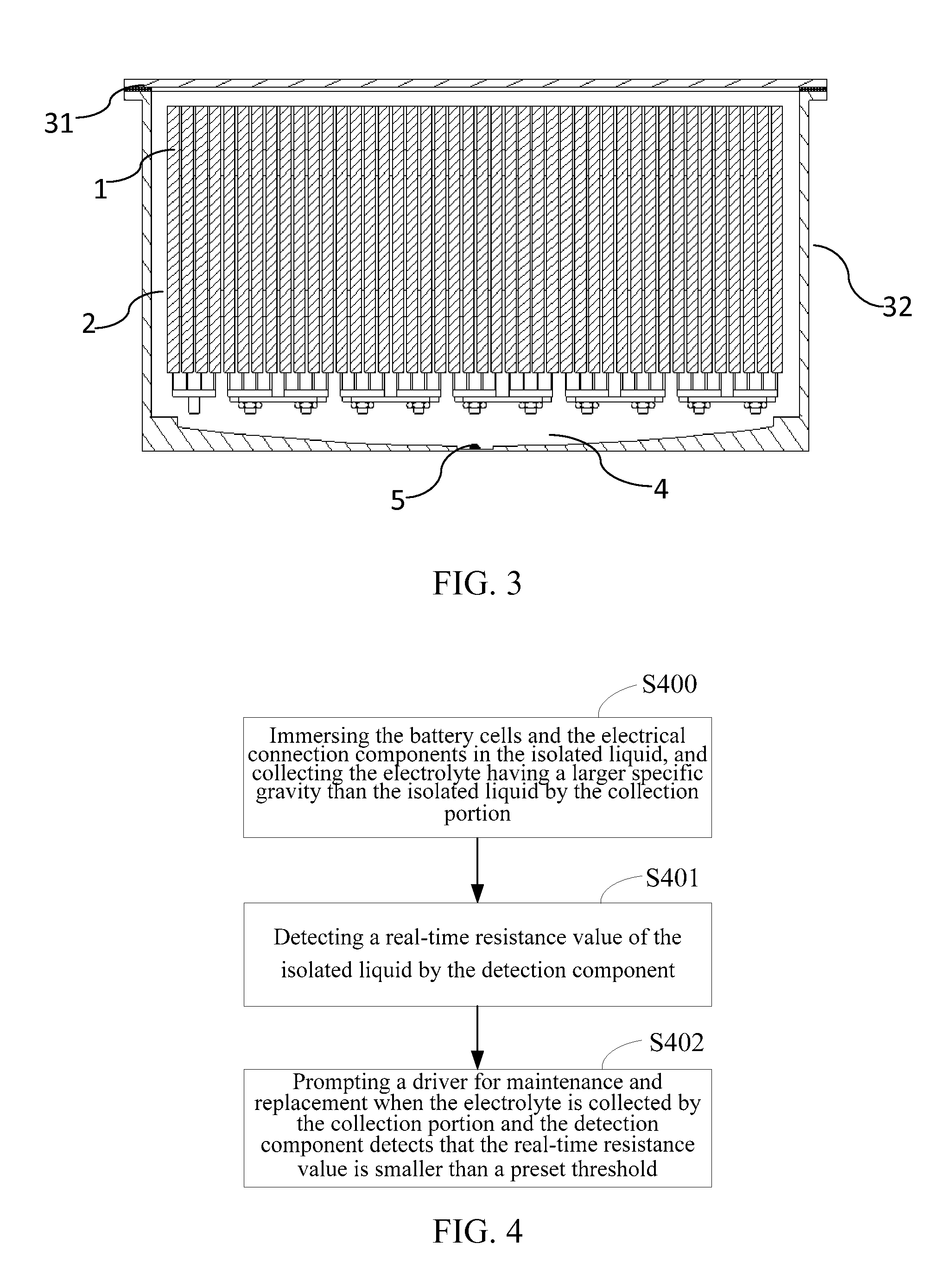
[0041]Referring to FIG. 4, the battery pack in this embodiment may be the battery pack described in the aforesaid embodiments. A liquid leakage detection method of a battery pack in this embodiment comprises, but is not limited to, the following steps of:

[0042]step S400: immersing the battery cells and the electrical connection components in the isolated liquid, and collecting the electrolyte having a larger specific gravity than the isolated liquid by the collection portion;

[0043]step S401: detecting a real-time resistance value of the isolated liquid by the detection component; and

[0044]step S402: prompting a driver for maintenance and replacement when the electrolyte is collected by the collection portion and the detection component detects that the real-time resistance value is smaller than a preset threshold. Specifically in the step S402, the preset threshold may be set depending on actual needs; e.g., to take corresponding measures against the problem in time, the preset thre...


PUM

PropertyMeasurementUnit
densityaaaaaaaaaa
specific gravityaaaaaaaaaa
electricalaaaaaaaaaa

Abstract

A battery pack and a liquid leakage detection method thereof are provided. The battery pack comprises a plurality of battery cells, a isolated liquid and a battery box containing the isolated liquid. The battery cells are soaked in the isolated liquid. The battery box comprising a box body and a cover plate. The isolated liquid is a fire-retardant and insulating liquid that has a specific gravity smaller than an electrolyte and is insoluble in the electrolyte. A collection portion is disposed at the bottom of the battery box, and a detection component is disposed in the collection portion. The present disclosure encloses the leaked electrolyte in the fire-retardant isolated liquid and uses the detection component to detect a resistance value of the isolated liquid so as to improve the safety of the box body.

Description

FIELD OF THE INVENTION[0001]The present disclosure relates to a battery pack, and further relates to a liquid leakage detection method of a battery pack.BACKGROUND OF THE INVENTION[0002]Currently, battery-driven electric vehicle and electric buses are gradually replacing conventional vehicle and buses. battery cells act as a main energy storage device in an electric vehicle. A battery box, as a device for containing the battery cells, is a key component of the electric vehicle, and has a direct influence on the performance of the battery cells and thus on the performance of the electric vehicle. As lithium-ion power batteries have advantages such as the excellent power output performance and a long service life, they have been widely applied in the electric vehicle[0003]The battery cells, as a main energy storage device in the electric vehicle, is generally consists of a plurality of batteries connected in series or in parallel. The batteries may be subject to liquid leakage after b...

Claims


Application Information

Patent Timeline
Patent Type & Authority Applications(United States)
IPC IPC(8): H01M10/48H01M50/209H01M50/24H01M50/264H01M50/271
CPCH01M2/1077H01M10/4228H01M10/484H01M10/482H01M10/488Y02E60/10H01M50/209H01M50/264H01M50/24H01M50/271
Inventor YANG, CONGMINGTONG, ZHIMINGLI, XIANGLI, HUI
Owner MICROVAST
Why Eureka
Try Eureka