Liquid consumption apparatus, liquid supply member, and liquid supply system

a technology of liquid consumption apparatus and liquid supply system, which is applied in the direction of printing, etc., can solve the problems of ink sticking around the vicinity of the removal port of the ink cartridge, inability to take into account the ink dripping ink leaking from the print apparatus side, so as to prevent the liquid from leaking, and facilitate the displacement of the rod member

Active Publication Date: 2013-07-18
SEIKO EPSON CORP
View PDF3 Cites 20 Cited by
  • Summary
  • Abstract
  • Description
  • Claims
  • Application Information

AI Technical Summary

Benefits of technology

[0009]According to the configuration of such description, even though liquid may leak out from a connecting portion connecting the liquid supply member and the liquid delivery unit, it is possible for the liquid to be caught by the liquid accepting unit, which is provided vertically below the liquid delivery unit, and to be guided to the first absorbent material. It is accordingly possible to more favorably cope with ink dripping during removal of the liquid supply member.
[0020]A liquid supply system according to another aspect includes the liquid supply member as set forth in the above described aspect, and a liquid storage unit configured to store the liquid being supplied to the liquid supply member. According to the configuration of such description, it is possible to increase the capacity of the liquid storage unit and thereby supply a large amount of the liquid to the liquid consumption apparatus.

Problems solved by technology

In such a print apparatus, in a case where the cartridge is removed from the print apparatus, there have conventionally been some cases where the ink may leak from a connecting portion that connects the print apparatus and the cartridge together.
However, the technologies set forth in Japanese Laid-Open Patent Publication No. 2002-178544 and Japanese Laid-Open Patent Publication No. 2010-158906 are technologies for preventing ink dripping on the cartridge side, and thus fail to take into account ink dripping from the print apparatus side.
Also, in the technology set forth in Japanese Laid-Open Patent Publication No. 2006-82292, there is a possibility that a case where ink has already been absorbed by the exposed section of the absorber body will result in the ink sticking around the vicinity of the removal port of the ink cartridge.

Method used


Image

  • Liquid consumption apparatus, liquid supply member, and liquid supply system
  • Liquid consumption apparatus, liquid supply member, and liquid supply system
  • Liquid consumption apparatus, liquid supply member, and liquid supply system

Examples


first modification example

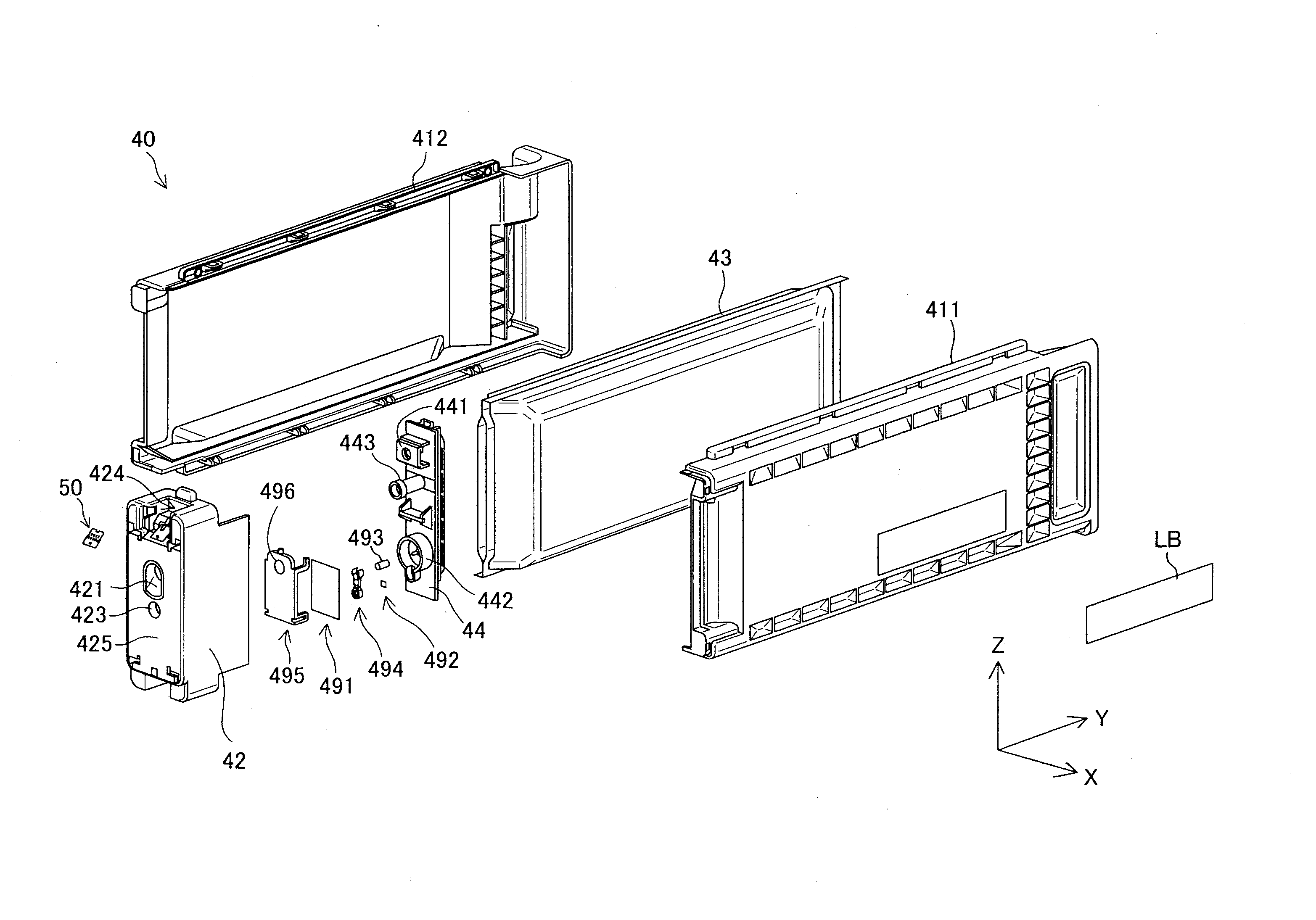
[0079]FIG. 12 is an exploded perspective view of an ink supply system 400 serving as a modification example of the cartridge 40. In the embodiment described above, the cartridge 40 was used to supply the ink to the print apparatus 10. By contrast, in the present modification example, the ink is supplied to the print apparatus 10 from a large-capacity ink tank 410. The ink supply system 400 is provided with the covering member 42, the liquid flow passage member 44, and the ink tank 410 which serves as a liquid storage unit. The covering member 42 and the liquid flow passage member 44 are identical to those in the embodiment described above. The ink tank 410 and the liquid flow passage member 44 are connected together via a tube 430. The ink tank 410 is filled with the ink, and the ink passes through the tube 430 and flows into the ink detection chamber 442 of the liquid flow passage member 44. In the present modification example, the ink detection chamber 442 is not essential; rather...

second modification example

[0082]In the embodiment described above, the ink accepting member 740 was moved toward the +Y-axis direction by the urging of the spring 750 during the removal of the cartridge 40. By contrast, the spring 750 may be omitted, the ink accept member 740 then being fixed to the ink delivery mechanism 70 so as not to move. The rod member 720 and / or the ink detection chamber 442 may also be omitted. In addition, the gutter member 743 may be formed of, for example, a tube.

third modification example

[0083]The present invention is not limited to a print apparatus or cartridge, and can also be applied to any desired liquid spray apparatus for spraying a liquid other thank ink, as well as to a liquid accommodation container therefor. For example, the present invention can be applied to a variety of liquid spray apparatuses and liquid accommodation containers therefor as follows.

[0084](1) An image recording apparatus, such as a facsimile

[0085](2) A color material spray apparatus used to produce a color filter for an image display device, such as a liquid crystal display

[0086](3) An electrode material spray apparatus used to form an electrode such as for an organic electroluminescence (EL) display or a field emission display (FED)

[0087](4) A liquid spray apparatus for spraying a liquid including a bio-organic material used to produce a bio-chip

[0088](5) A sample spray apparatus that serves as a precision pipette

[0089](6) An apparatus for spraying lubricating oil

[0090](7) An apparatu...


PUM


Abstract

A liquid consumption apparatus, onto which a liquid supply member is mounted, includes a liquid delivery unit, a liquid accepting unit and an abutting section. The liquid delivery unit is configured to deliver a liquid from the liquid supply member. The liquid accepting unit is provided below the liquid delivery unit. The abutting section abuts against the liquid supply member. The liquid accepting unit is provided to the abutting section. In a state where the abutting section and the liquid supply member abut against each other, the liquid accepting unit protrudes out closer toward the liquid supply member than a surface where the liquid supply member and the abutting section abut against each other.

Description

CROSS-REFERENCE TO RELATED APPLICATIONS[0001]This application claims priority to Japanese Patent Application No. 2012-022822 filed on Feb. 6, 2012, Japanese Patent Application No. 2012-005347 filed on Jan. 13, 2012, and Japanese Patent Application No. 2012-013238 filed on Jan. 25, 2012. The entire disclosures of Japanese Patent Application Nos. 2012-022822, 2012-005347 and 2012-013238 are hereby incorporated herein by reference.BACKGROUND[0002]1. Technical Field[0003]The present invention relates to a liquid consumption apparatus.[0004]2. Related Art[0005]In general, a print apparatus that uses ink as a print material has mounted therein a cartridge in the interior of which the ink is accommodated. In such a print apparatus, in a case where the cartridge is removed from the print apparatus, there have conventionally been some cases where the ink may leak from a connecting portion that connects the print apparatus and the cartridge together. In order to cope with such ink leakage, fo...

Claims


Application Information

Patent Timeline
Patent Type & Authority Applications(United States)
IPC IPC(8): B41J2/17B41J2/175
CPCB41J2/1721B41J2/17553B41J2/17523B41J2/1752B41J2/17509
Inventor AOKI, YUJISATOH, HIROSHI
Owner SEIKO EPSON CORP
Why Eureka
Try Eureka