Camera module and image capturing device

Active Publication Date: 2013-07-18
SHARP KK
View PDF9 Cites 16 Cited by
  • Summary
  • Abstract
  • Description
  • Claims
  • Application Information

AI Technical Summary

Benefits of technology

[0024]As described above, a camera module of the present invention includes: optical means including a lens section made of at least one optical lens; sensor means including an image pickup element converting, into an electrical signal, light that enters the image pickup element through the lens section; and image stabilization means correcting misalignment of an optical axis with respect to the image pickup element, by shifting relative positions of the optical means and the sensor means in parallel to an image pickup plane of the image pickup element in accordance with an inclination of a main body of the camera module, the lens section having an image height-optical distortion curve

Problems solved by technology

Accordingly, the conventional camera module 200 had a problem in that a significant change occurs in perspective in a peripheral p

Method used


Image

  • Camera module and image capturing device
  • Camera module and image capturing device
  • Camera module and image capturing device

Examples


Example

[0043]The following discusses one embodiment of a camera module of the present invention, with reference to FIGS. 1 thorough 8. The present embodiment discusses a camera module that includes an optical image stabilizer (OIS) of a sensor-shift system. In the following explanation, the present embodiment is given various limitations that are technically preferable for carrying out the present invention. However, the scope of the present invention is by no means limited to the following embodiments and attached drawings.

[1] CONFIGURATION OF CAMERA MODULE

[0044]First, the following explains a configuration of a camera module of the present embodiment, with reference to FIGS. 1 and 2.

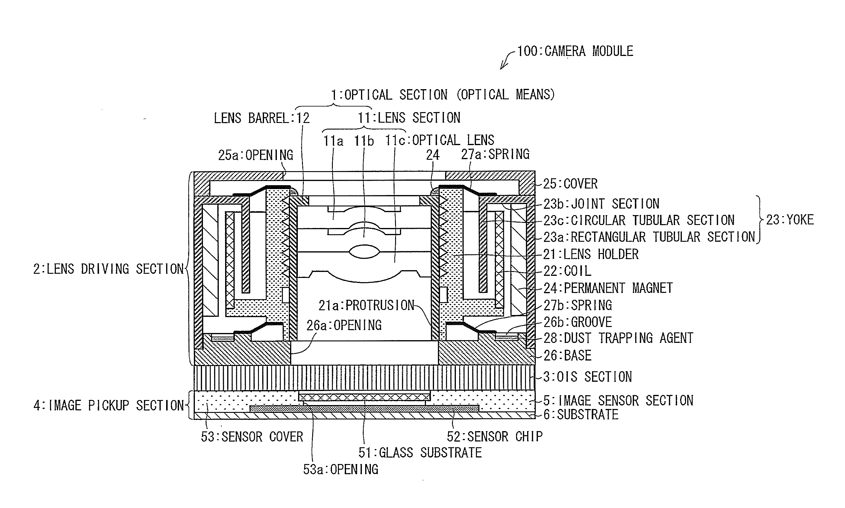
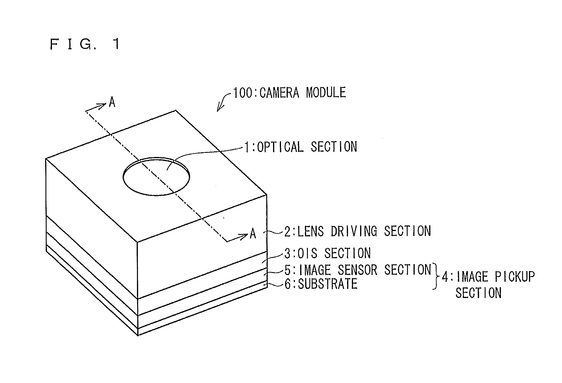
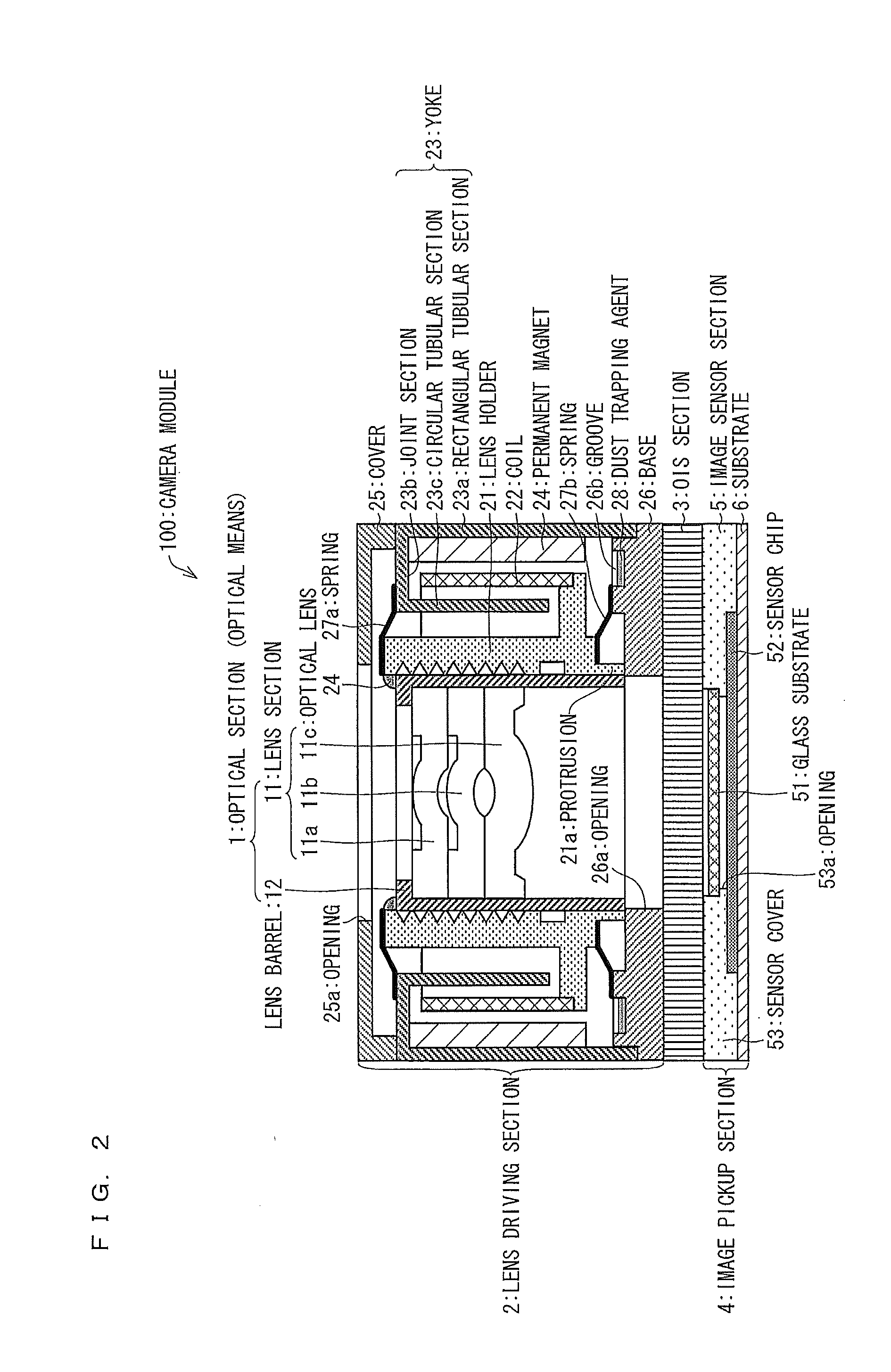
FIG. 1 is a perspective view illustrating an appearance configuration of a camera module 100 of the present embodiment. As illustrated in FIG. 1, the camera module 100 includes an optical section (optical means) 1 that is an optical imaging system, a lens driving section 2 that drives the optical section 1, a...


PUM


Abstract

A camera module (100) of the present invention includes: an optical section (1) including a lens section (11); and an OIS section (3) correcting misalignment of an optical axis. The lens section (11) has an image height-optical distortion curve in which an optical distortion is a positive maximum value in an intermediate image height region and the optical distortion gradually decreases from the maximum value as an image height approaches a maximum image height.

Description

TECHNICAL FIELD[0001]The present invention relates to a camera module, more specifically, a camera module including an optical image stabilizer of a lens-shift system or a sensor-shift system.BACKGROUND ART[0002]Conventionally, an imaging device, such as a digital video camera and a digital still camera, that includes an optical image stabilizer (hereinafter, referred to as OIS) has been in practical use. The OIS is a mechanism for correcting burring that occurs in a captured image due to camera shake.[0003]The OIS includes a gyro sensor that detects, in terms of an angular velocity, etc., an inclination of an imaging device which inclination is caused by camera shake. Then, the OIS corrects misalignment of an optical axis with respect to a light-receiving section of an image sensor, by shifting, in accordance with an output signal from the gyro sensor, a lens or an image sensor such as a CCD in a vertical direction with respect to the optical axis, that is, in parallel to the light...

Claims


Application Information

Patent Timeline
IPC IPC(8): H04N5/232G02B13/00G03B5/00G03B7/00H04N5/225
CPCG02B13/0035G03B3/02H04N5/2257G03B2205/0038G03B5/02G03B2205/0015H04N5/23287H04N23/57H04N23/687
Inventor ISHIZUE, YOSHIHITO
Owner SHARP KK
Why Eureka
Try Eureka