Hybrid vehicle driving apparatus

a driving apparatus and hybrid technology, applied in the direction of engine-driven generators, transportation and packaging, transportation, etc., can solve the problems of reducing the accuracy of supporting the first electric means, increasing the weight of the vehicle or the cost, etc., to achieve the effect of reducing the number of components, improving the accuracy of supporting, and reducing the weigh

Active Publication Date: 2013-07-18
TOYOTA JIDOSHA KK +1
View PDF4 Cites 22 Cited by
  • Summary
  • Abstract
  • Description
  • Claims
  • Application Information

AI Technical Summary

Benefits of technology

[0008]The invention provides a hybrid vehicle driving apparatus in which the supporting accuracy of rotating shafts supported by a casing that is made up of a plurality of case members is improved.
[0010]In the first aspect of the invention, the output gear shaft, the power transmission shaft, the counter shaft, the differential gear, the first rotor shaft, and the second rotor shaft of the second electric motor are supported by the case member (common case member) that is common to those shafts and the differential gear. This improves the accuracy of supporting those rotating shafts and the differential gear. Furthermore, since the shafts and the differential gear are all supported by the common case member, increases in the number of component parts and increases in the weight can be restrained.

Problems solved by technology

If the rotor shaft is supported by the center support, the accuracy of supporting the first electric means declines due to the mounting error of the center support.
In addition, since the number of component parts increases, the weight of the vehicle or cost may increase.

Method used


Image

  • Hybrid vehicle driving apparatus
  • Hybrid vehicle driving apparatus
  • Hybrid vehicle driving apparatus

Examples


first embodiment

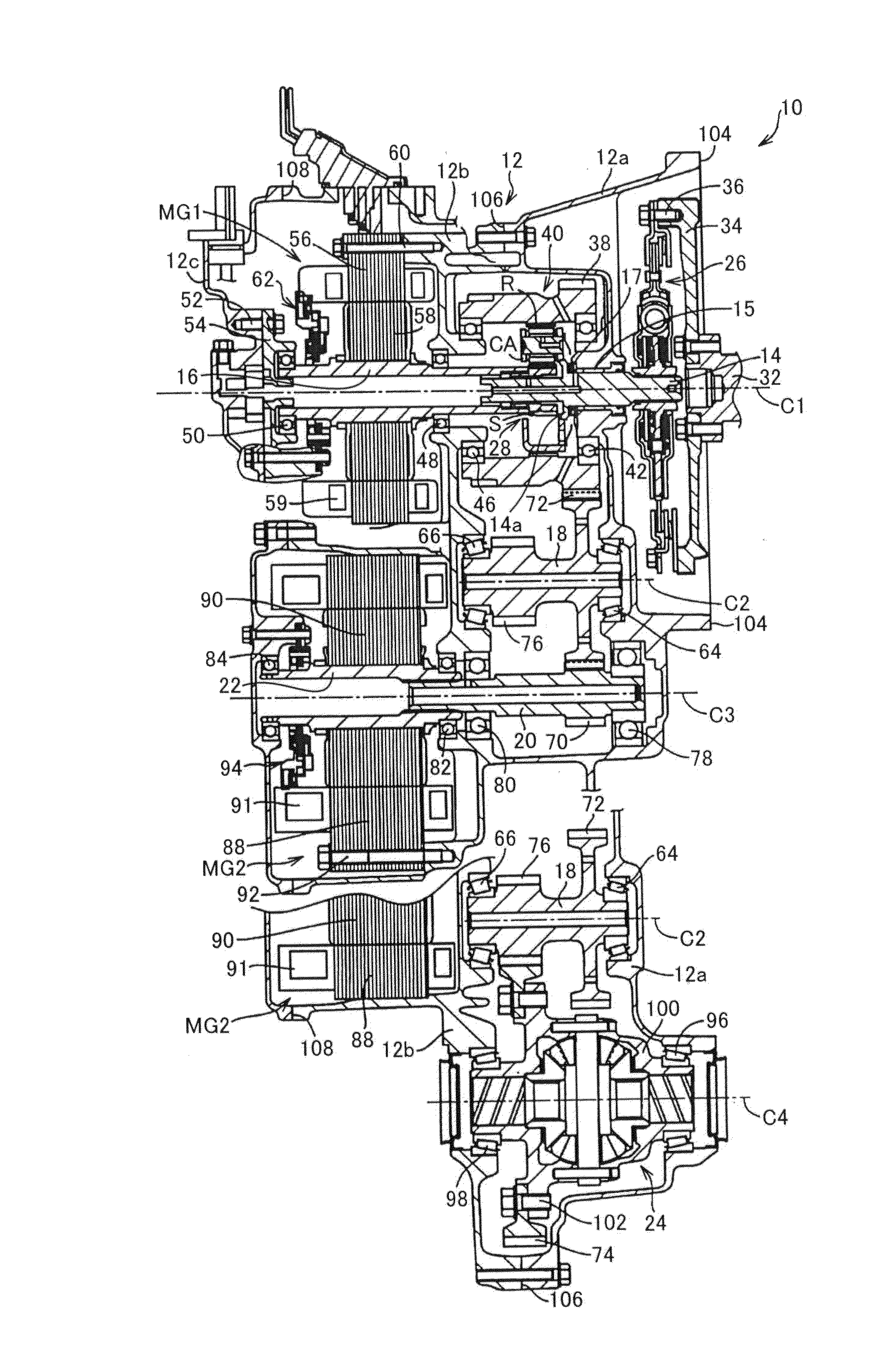
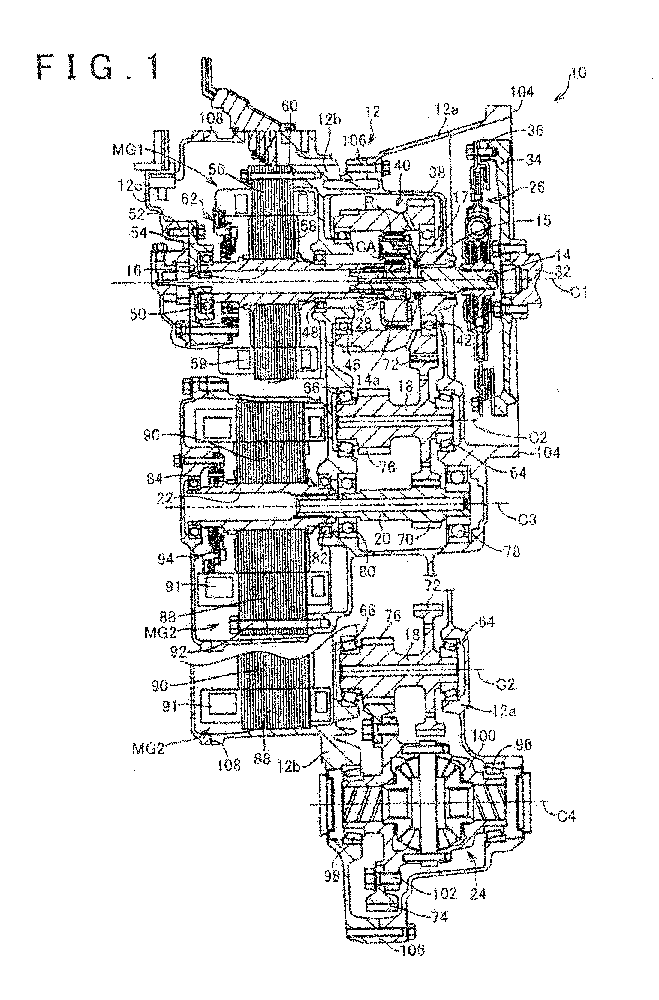
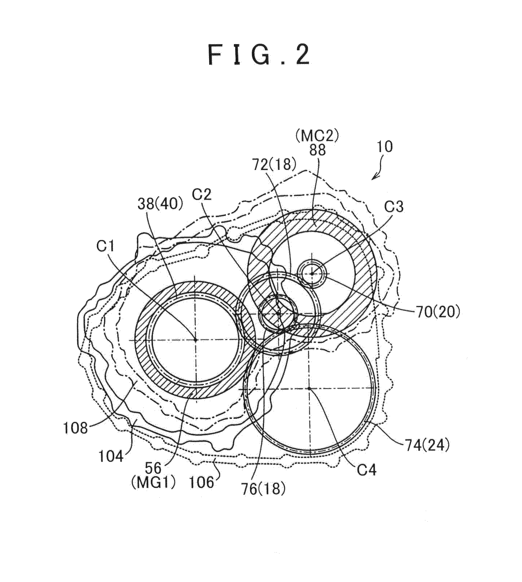
[0016]FIG. 1 is a sectional view illustrating a structure of a hybrid vehicle driving apparatus 10 in accordance with the invention. The hybrid vehicle driving apparatus 10 (hereinafter, the driving apparatus 10) has four rotation axes (C1 to C4) in a casing 12. On a first axis C1, there are an input shaft 14, a power distribution mechanism 28 and a first rotor shaft 16 of a first electric motor MG1 that are rotatably supported. A counter shaft 18 is rotatably supported on a second axis C2. A power transmission shaft 20 and a second rotor shaft 22 of a second electric motor MG2 are rotatably supported on a third axis C3. On a fourth axis C4, a differential gear 24 is rotatably supported. The first axis C1, the second axis C2, the third axis C3 and the fourth axis C4 are parallel to each other.

[0017]The casing 12 is constructed of three case members, which are a housing 12a, a case 12b and a cover 12c. End surfaces (joining surfaces) of the case members in the axis direction are fast...

second embodiment

[0063]As described above, since the composite gear shaft 154, the power transmission shaft 158, the counter shaft 18, the differential gear 24, the first rotor shaft 156 of the first electric motor MG1, the second rotor shaft 160 of the second electric motor MG2 are supported by a common member, that is, the case member 164, the accuracy of supporting the rotating shafts will improve. Furthermore, since these shafts and the like are all supported by a common member, that is, the case member 164, increases in the number of component parts and increases in the weight are restrained.

[0064]Furthermore, according to the second embodiment, the outer wheel of the sixth bearing 66 that supports the counter shaft 18, the outer wheel of the third bearing 48 that supports the first rotor shaft 156 of the first electric motor MG1, and the outer wheel of the ninth bearing 82 that supports the second rotor shaft 160 of the second electric motor MG2 are press-fitted into the case 164. Due to this...


PUM


Abstract

A hybrid vehicle driving apparatus includes: a first rotor shaft of a first electric motor, the first electric motor being disposed on a first axis; a power distribution mechanism that includes a planetary gear device and is disposed on the first axis; an output gear shaft that serves as an output member of the power distribution mechanism and is disposed on the first axis; a counter shaft disposed on a second axis; a second rotor shaft of a second electric motor disposed on a third axis; a power transmission shaft disposed on the third axis; a differential gear disposed on a fourth axis; and a casing that includes a plurality of case members. The output gear shaft, the power transmission shaft, the counter shaft, the differential gear, the first rotor shaft, and the second rotor shaft are rotatably supported by a common case member that is one of the plurality of case members.

Description

INCORPORATION BY REFERENCE[0001]The disclosure of Japanese Patent Application No. 2011-158435 filed on Jul. 19, 2011 including the specification, drawings and abstract is incorporated herein by reference in its entirety.BACKGROUND OF THE INVENTION[0002]1. Field of the Invention[0003]The invention relates to a hybrid vehicle driving apparatus.[0004]2. Description of Related Art[0005]There is known a hybrid vehicle driving apparatus which includes a rotor shaft of a first electric motor that is disposed on a first axis, a power distribution mechanism that includes a planetary gear device is disposed on the first axis, and an output gear shaft that serves as an output member of the power distribution mechanism on the first axis. The hybrid vehicle driving apparatus also includes a counter shaft that is disposed on a second axis, a rotor shaft of a second electric motor that is disposed on a third axis, a power transmission shaft that is disposed on the third axis, and a differential ge...

Claims


Application Information

Patent Timeline
Patent Type & Authority Applications(United States)
IPC IPC(8): F16H37/08B60L50/16
CPCB60K6/40F16H37/0826Y02T10/6239B60K6/445B60K6/405Y02T10/62
Inventor TSUCHIDA, MICHITAKANISHIZURU, TOMOAKIOBATA, TATSUOSADA, NATSUKIYATA, HIROTAKAATARASHI, TOMOO
Owner TOYOTA JIDOSHA KK
Why Eureka
Try Eureka