
Methods of implant of a heart valve with a convertible sewing ring

a technology of sewing ring and heart valve, which is applied in the field of medical devices, can solve the problems of less than perfect shape of the resulting annulus for the attachment of sewing ring, requires a great deal of skill and concentration, and difficult to achieve the effect of ensuring the safety of the patient, easy isolation of sewing ring, and easy to manufacture and implantation of heart valves

Inactive Publication Date: 2013-07-18
EDWARDS LIFESCIENCES CORP
View PDF3 Cites 42 Cited by
  • Summary
  • Abstract
  • Description
  • Claims
  • Application Information

AI Technical Summary

Benefits of technology

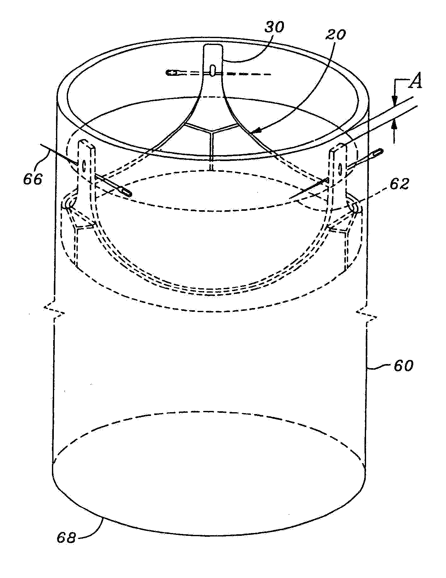
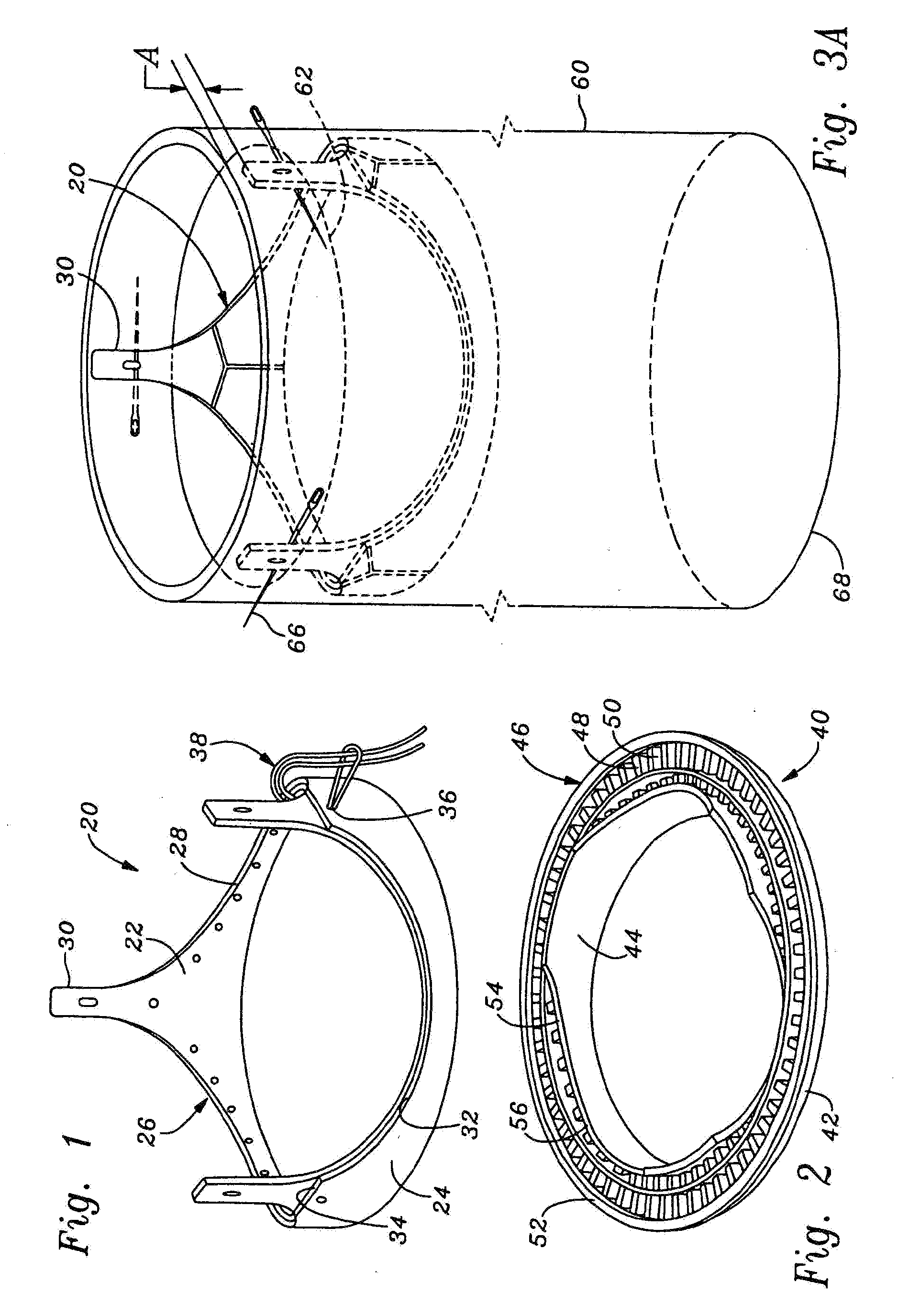
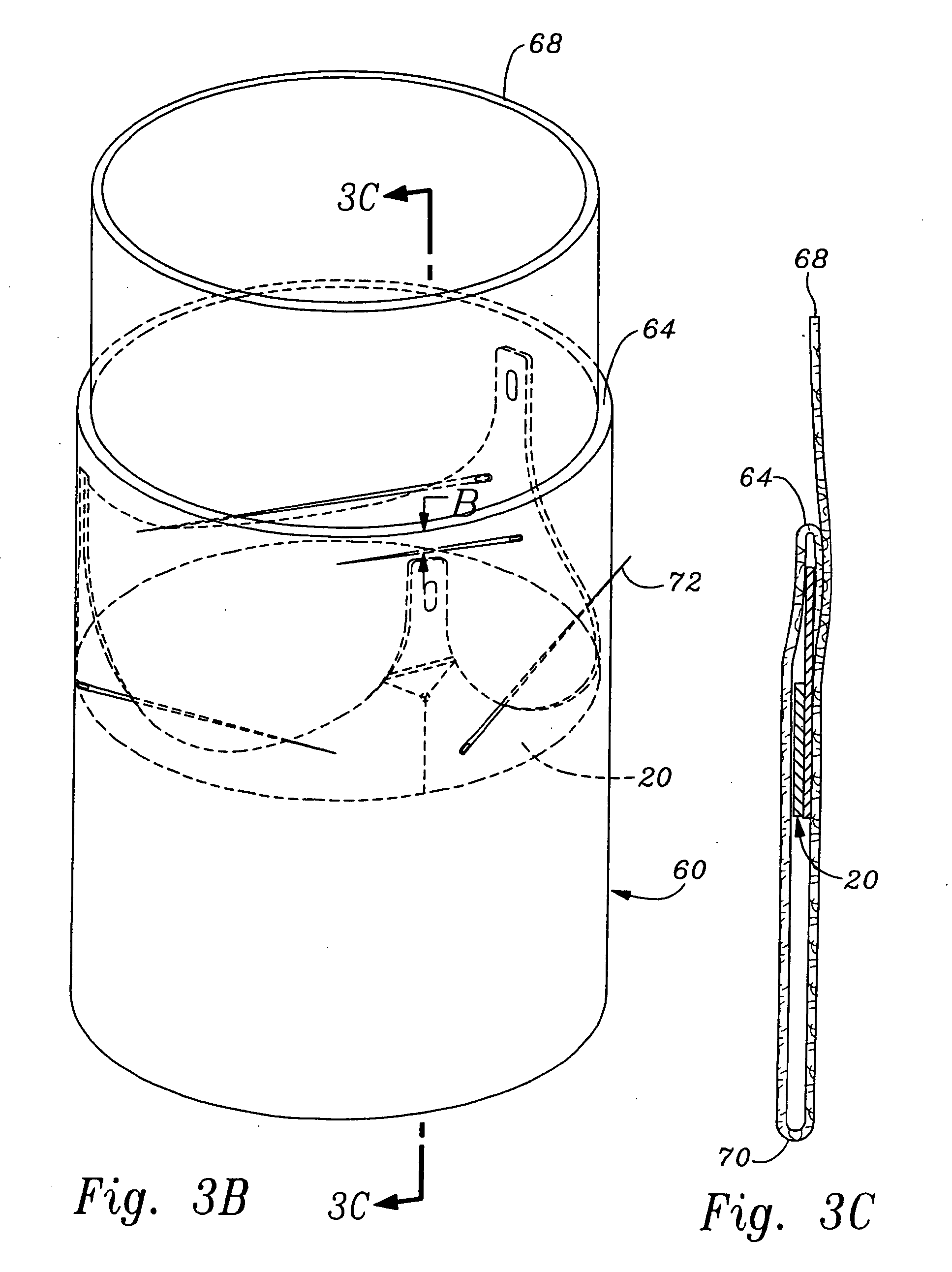
[0009]The present invention provides an improved sewing ring and sewing ring / stent assembly that facilitates manufacture and implantation of heart valves. The sewing ring is adapted to pivot or move outward from the stent, thus enabling a surgeon during the implantation procedure to more easily isolate the sewing ring against the native tissue and away from the stent and tissue leaflets. Thus, there is less chance of the surgeon puncturing the leaflets. Furthermore, the compliance of the sewing ring, or ability to pivot the ring away from the stent, enables the sewing ring to be made smaller in the radial dimension, and thus the overall valve orifice size can be increased. Additionally, the manufacturing process is facilitated because various regions around the stent can be more easily visualized and accessed by virtue of the movable sewing ring.
[0011]In a further aspect, a heart valve having an inflow end and an outflow end is provided, comprising a generally annular stent, and a suture-permeable sewing ring attached to a periphery thereof. The sewing ring is movable between two positions, wherein in the first position the sewing ring extends generally toward the outflow end of the valve and in the second position the sewing ring extends generally toward the inflow end of the valve. The sewing ring may comprise an insert ring and a fabric cover, and the fabric covering the insert ring may also cover a portion of the stent. In a preferred embodiment, the sewing ring attaches to the stent exclusively with a portion of a fabric that also covers a portion of the sewing ring. A seam is desirably provided in the fabric at the line of attachment between the sewing ring and the stent, wherein the sewing ring pivots about the seam between the first and second positions. The first and second positions may be stable, and the insert ring may be frustoconical in shape such that in the first position the ring extends toward the outflow end and in the second position the ring extends toward the inflow end. Furthermore, the insert ring may be provided with alternating radially thick and thin regions, or it may have a radially unulating shape, to facilitate movement between the first and second positions.

Problems solved by technology

The time and spacial constraints imposed by surgery, however, often dictate that the shape of the resulting annulus is less than perfect for attachment of a sewing ring.
Mattress sutures are more time consuming and essentially comprise double passes of the needle through the tissue with one knot.
Naturally, the implantation of a prosthetic heart valve, either a mechanical valve or a bioprosthetic valve (i.e., “tissue” valve), requires a great deal of skill and concentration given the delicate nature of the native heart tissue, the spatial constraints of the surgical field and the criticality of achieving a secure and reliable implantation.

Method used


Image

  • Methods of implant of a heart valve with a convertible sewing ring
  • Methods of implant of a heart valve with a convertible sewing ring
  • Methods of implant of a heart valve with a convertible sewing ring

Examples


Embodiment Construction

[0039]The present invention provides an improved heart valve sewing ring that enables an increase in the effective orifice size of the valve without increasing the overall valve outer diameter. Sewing rings for a mitral heart valve and an aortic heart valve are illustrated herein, but those of skill in the art will understand that many of the inventive concepts are applicable to heart valves for the pulmonary or tricuspid valve positions. More specifically, the annulus for the mitral and tricuspid positions are generally planar and non-scalloped, while the annulus for the aortic and pulmonary positions are generally scalloped or undulating (i.e., three dimensional). Therefore, certain sewing ring features disclosed herein may be more or less suitable to a planar or scalloped annulus. Moreover, although certain features are described as particularly suited to either the mitral (planar annulus) or aortic (scalloped annulus) valve designs, such features in other constructions may be ap...


PUM


Abstract

A sewing ring for prosthetic heart valves that is connected and configured to pivot outward. A biocompatible fabric covering surrounds at least a portion of the sewing ring, and the ring may be exclusively connected to a stent with the fabric. The sewing ring may be generally planar and of uniform thickness, or may be of varying thickness. The fabric may be used to encompass both the stent and the sewing ring, and may be a single piece. A seam may be provided in the fabric as a discrete pivoting line. The sewing ring may be convertible between bi-stable positions. The ring may extend outward in a frusto-conical shape so as to enable inversion between a position facing the inflow end of the valve and a position facing the outflow end of the valve. A method of implantation, and a method of assembly of the heart valve is also provided.

Description

RELATED APPLICATIONS[0001]The present application is a divisional of U.S. application Ser. No. 10 / 802,314, filed Mar. 17, 2004, which in turn is a continuation of U.S. application Ser. No. 09 / 585,098, filed Jun. 1, 2000, now abandoned.FIELD OF THE INVENTION[0002]The present invention relates generally to medical devices and particularly to methods of implant of a prosthetic heart valve having a convertible sewing ring.BACKGROUND OF THE INVENTION[0003]Prosthetic heart valves are used to replace damaged or diseased heart valves. In vertebrate animals, the heart is a hollow muscular organ having four pumping chambers: the left and right atria and the left and right ventricles, each provided with its own one-way valve. The natural heart valves are identified as the aortic, mitral (or bicuspid), tricuspid and pulmonary valves. Prosthetic heart valves can be used to replace any of these naturally occurring valves, although repair or replacement of the aortic or mitral valves is most commo...

Claims


Application Information

Patent Timeline
Patent Type & Authority Applications(United States)
IPC IPC(8): A61F2/24
CPCA61F2/2445A61F2/2409A61F2/2412A61F2220/0075A61F2230/0067
Inventor HUYNH, VAN LESCOTT, MICHAEL J.JOHNSON, DERRICK
Owner EDWARDS LIFESCIENCES CORP
Learn More