
Tread for winter-use pneumatic tires

a pneumatic tire and tread technology, applied in the direction of non-skid devices, vehicle components, transportation and packaging, etc., can solve the problems of reducing the area of the ground contacting surface of the blocks, deteriorating the durability insufficient maintenance of the tread pattern, so as to achieve effective enhancement of the tread pattern durability and generate more heat

Inactive Publication Date: 2013-07-25
MICHELIN & CO CIE GEN DES ESTAB MICHELIN +1
View PDF6 Cites 16 Cited by
  • Summary
  • Abstract
  • Description
  • Claims
  • Application Information

AI Technical Summary

Benefits of technology

This patent describes a new design for tire blocks that helps improve the durability of tire patterns. By creating small holes in a specific area, the blocks have better rigidity and are less likely to break down over time. This design also helps to dissipate heat and prevent damage to the material caused by heat, which further enhances the durability of the tire pattern.

Problems solved by technology

However, with the technique disclosed in Patent literature article 1 there is the problem that durability of the tread pattern cannot be adequately maintained, predominantly as a result of the disposition of the sipes and the disposition of the small holes.
Further, there is a problem with the elliptical small holes disclosed in Patent literature article 2 in that there is concern that the durability of the tread pattern may be deteriorated by concentration of stress at the elliptical end portions when the tire is rotating.
Further, with the technique disclosed in Patent literature article 3 there is the problem that provision of relatively thick sipes causes the area of the ground contacting surface of the blocks to be reduced, deteriorated the performance on ice.

Method used


Image

  • Tread for winter-use pneumatic tires
  • Tread for winter-use pneumatic tires
  • Tread for winter-use pneumatic tires

Examples


Embodiment Construction

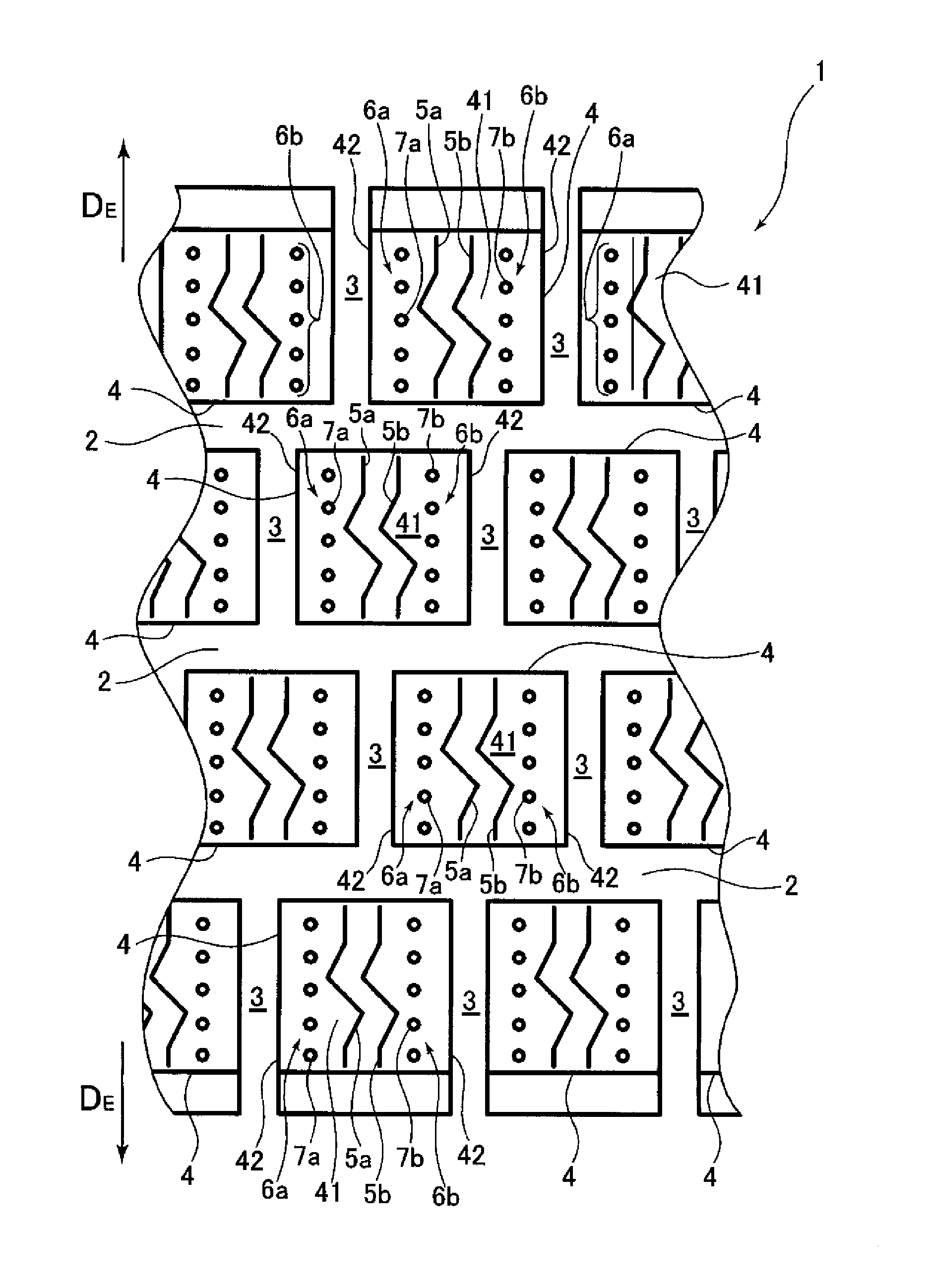
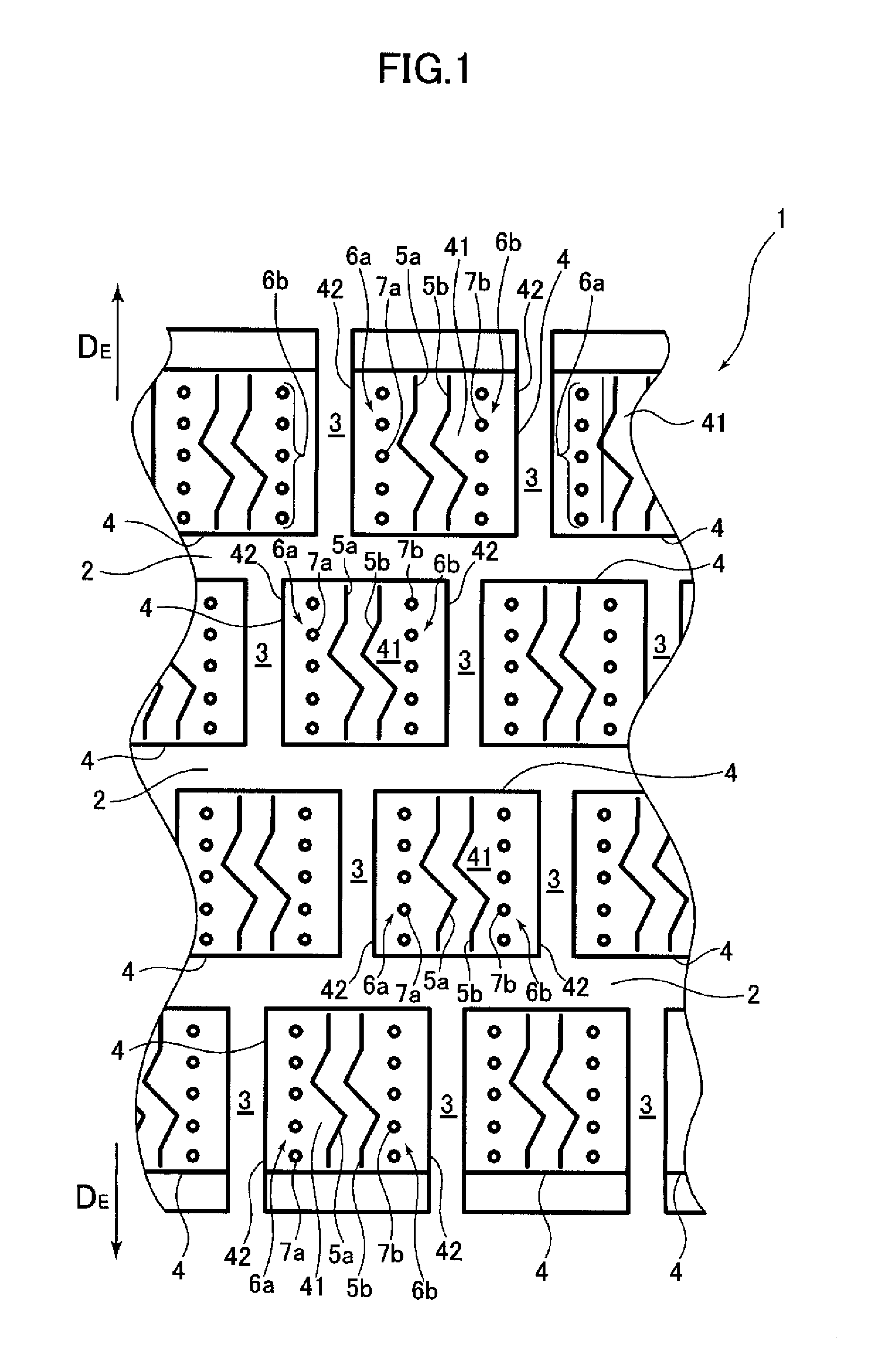
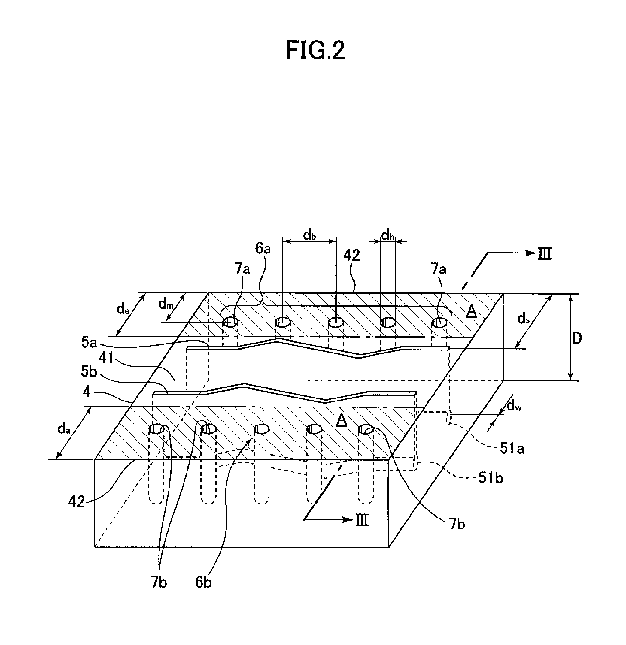
[0039]Preferred modes of embodiment of the present invention will now be described with reference to the diagrams. First, a tread for a winter-use pneumatic tire according to a first mode of embodiment of the present invention will be described based on FIG. 1 to FIG. 3. FIG. 1 is a diagram illustrating schematically a tread for a winter-use pneumatic tire according to a first mode of embodiment of the present invention, FIG. 2 is a diagram illustrating schematically a block in the tread for a winter-use pneumatic tire according to the first mode of embodiment of the present invention, and FIG. 3 is an enlarged sectional view of the tread for a winter-use tire as viewed along line III-III in FIG. 2.

[0040]First, as shown in FIG. 1, reference number 1 indicates a winter-use pneumatic tire tread according to a first mode of embodiment. It should be noted that the size of the tire in this example is 205 / 55R16. In the tread 1 are formed three circumferential grooves 2 extending in the ci...


PUM


Abstract

To provide a winter-use pneumatic tire with which the performance on ice can be enhanced and tread pattern durability can be enhanced. The tread for a winter-use pneumatic tire according to the present invention has blocks which are aligned in the circumferential direction and in which are formed respectively at least one thin incision which extends substantially parallel to a circumferential direction edge and which has a widened portion at its bottom, and at least one series of small holes comprising at least two small holes which open in a ground contacting surface of the block and extend in the inward radial direction of the tire, and the at least one series of small holes is formed in a neighboring region of the circumferential direction edge, and is formed in an intermediate portion between the circumferential direction edge and the at least one thin incision.

Description

TECHNICAL FIELD [0001]The present invention relates to a tread for a winter-use pneumatic tire, and in particular relates to a tread for a winter-use pneumatic tire which has a plurality of blocks demarcated by circumferential grooves and transverse grooves.BACKGROUND ART[0002]The treads of winter-use pneumatic tires predominantly employ block patterns, and performance on snow is enhanced by snow becoming caught in spaces between two blocks that are adjacent in the direction of rotation of the tire. Also, performance on ice is enhanced by means of a so-called edge effect and by an effect of removing a water film on the ice surface by providing these blocks with a plurality of so-called sipes which extend in the width direction of the tire.[0003]As means for further enhancing the performance on ice there are known techniques whereby the density of the sipes provided in the blocks is increased, and the edge effect and the effect of removing the water film on the ice surface are enhanc...

Claims


Application Information

Patent Timeline
IPC IPC(8): B60C11/03
CPCB60C11/0302B60C11/032B60C2011/1213B60C11/1236B60C2011/1254B60C11/0306B60C11/1281
Inventor KANEKO, SHUICHI
Owner MICHELIN & CO CIE GEN DES ESTAB MICHELIN
Learn More