
Ink jet printing method and printer

a printing method and printer technology, applied in printing, other printing apparatus, etc., can solve the problems of nozzle failure, a serious threat to print quality, and a single pass process is particularly vulnerable to nozzle failure, so as to improve the reliability of ink jet printing

Active Publication Date: 2013-07-25
OCE TECH
View PDF5 Cites 10 Cited by
  • Summary
  • Abstract
  • Description
  • Claims
  • Application Information

AI Technical Summary

Benefits of technology

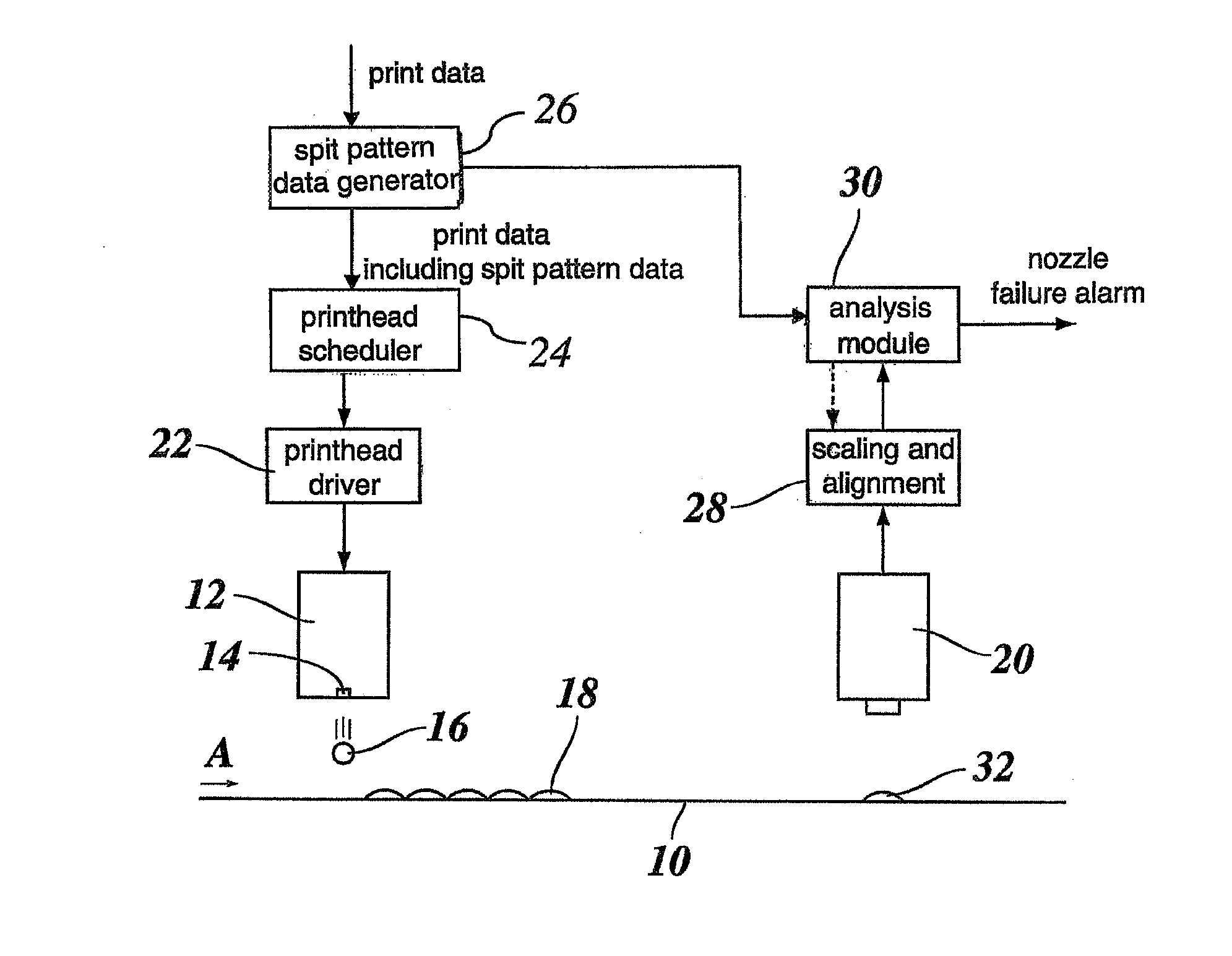
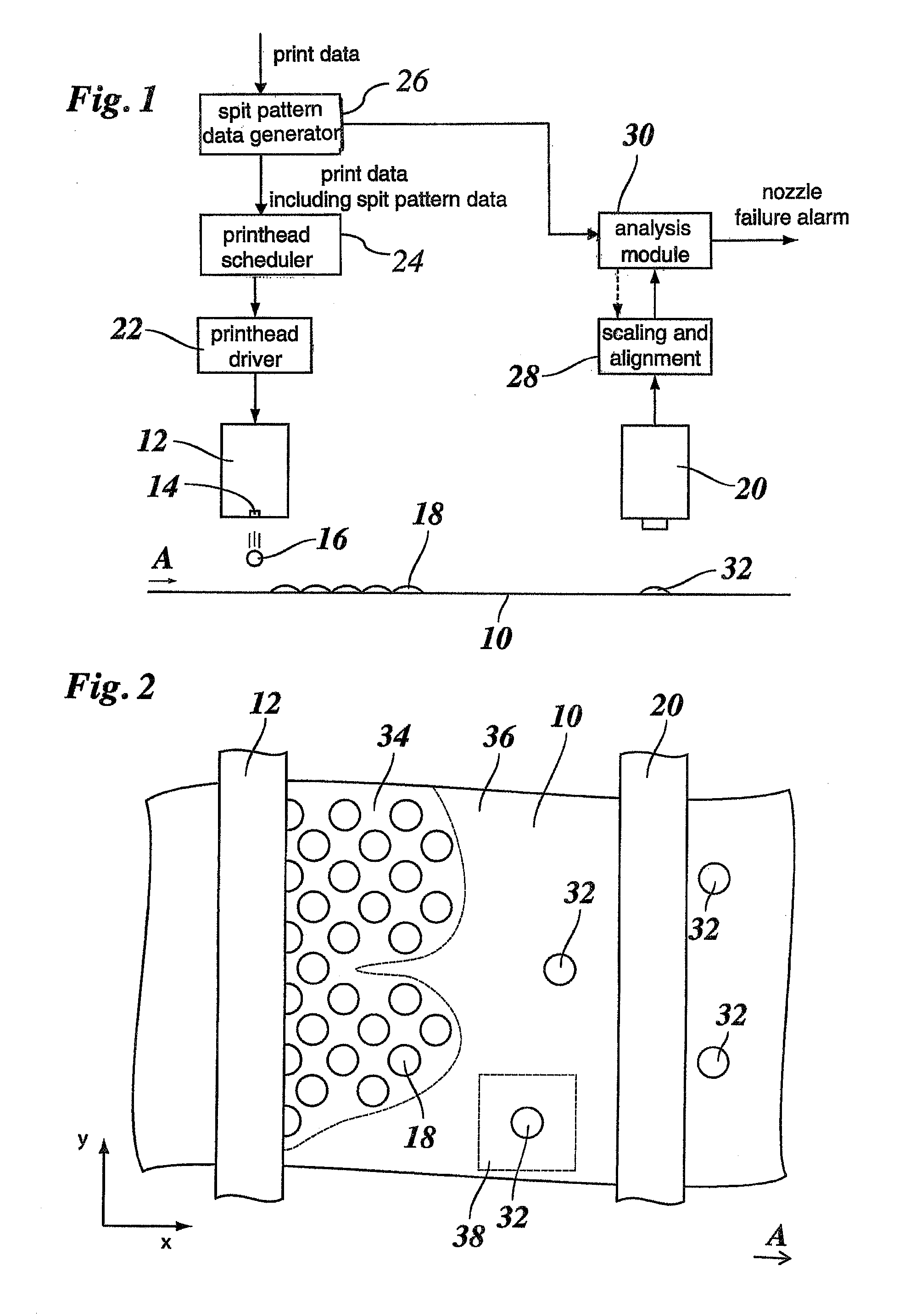
The present invention is a method for improving the reliability of ink jet printing by combining nozzle failure prevention and detection. The method uses spit pattern data to specify the locations where ink dots are expected to be printed. The spit pattern data prevents nozzle failures by shortening the intervals in which the nozzles are inactive and detects nozzle failures by verifying the presence of dots in the specified locations. This approach is applicable to the highly efficient single-pass print process. The spit pattern data also serves as an isolated ink dot in the background of an image, making it easier to detect and identify the responsible nozzle. Even if a nozzle is not needed for printing a particular portion of the image, it may be activated from time to time to detect nozzle failure before it is needed again. The spit pattern data may be static or dynamic, depending on the print data.

Problems solved by technology

In ink jet printing, nozzle failures may be caused by nozzle clogging, contamination of a plate in which the nozzles are formed, events in which the nozzles are touched by the recording medium, and the like.
Such nozzle failures are a serious threat to reliable ink jet printing and to print quality.
Such a single pass process is particularly vulnerable to nozzle failures because there are only limited possibilities to compensate nozzle failures by printing extra dots with other, still intact nozzles of the print head.
It is known that the risk of nozzle failures increases when a nozzle is inactive for a certain time, because the ink may dry-out in the nozzle.
However, this method implies a waste in paper and ink, especially when the test is repeated in short intervals.
However, depending on the nature of the print data, it may be difficult to detect nozzle failures, and when a nozzle failure occurs at a nozzle that is not currently used for printing, the failure cannot be detected before the nozzle is used again.

Method used


Image

  • Ink jet printing method and printer
  • Ink jet printing method and printer

Examples


Embodiment Construction

[0027]The present invention will now be described with reference to the accompanying drawings, wherein the same or similar elements are identified with the same reference numeral.

[0028]As is shown in FIG. 1, a recording medium 10, e.g. a sheet of paper, is moved with a constant speed in the direction of an arrow A by means of a transport mechanism, that has not been shown. A print head 12 having a plurality of nozzles 14 is disposed above the path of the recording medium 10 and extends over the entire width of the recording medium (in the direction normal to the plane of the drawing in FIG. 1). As is generally known in the art, the nozzles 14 have actuators configured to cause the nozzles to eject ink droplets 16 onto the recording medium 10 so as to print an image composed of ink dots 18 in accordance with print data supplied to the print head. The nozzles 14 are arranged in one or more lines across the width of the recording medium in a certain raster that defines the print resolu...


PUM


Abstract

In an ink jet printing method, a recording medium is moved relative to a print head having a plurality of nozzles, and ink droplets are ejected from the nozzles onto the recording medium in a single pass in accordance with print data supplied to the print head. Spit pattern data is included in the print data A location of an expected ink dot ejected according to the spit pattern data is scanned, providing a scanned image, and such ink dot is searched for in the scanned image in order to determine an actual presence of the ink dot.

Description

CROSS-REFERENCE TO RELATED APPLICATIONS[0001]This application is a Continuation of International Application No. PCT / EP2011 / 066840, filed on Sep. 28, 2011, and for which priority is claimed under 35 U.S.C. § 120, and which claims priority under 35 U.S.C. § 119 to Application No. 10186868.5, filed in Europe on Oct. 7, 2010. The entirety of each of the above-identified applications is expressly incorporated herein by reference.BACKGROUND OF THE INVENTION[0002]1. Field of the Invention[0003]The present invention relates to an ink jet printing method, wherein a recording medium is moved relative to a print head having a plurality of nozzles, the method comprising the steps of adding spit pattern data to print data to be printed by the print head, supplying the print data and the added spit pattern data to the print head, and ejecting ink droplets from the nozzles onto the recording medium in accordance with the print data and the spit pattern data in a single pass of the recording mediu...

Claims


Application Information

Patent Timeline
Patent Type & Authority Applications(United States)
IPC IPC(8): B41J2/045
CPCB41J2/16526B41J2/0451B41J2/2139B41J2/2052
Inventor DE SMET, SEBASTIAN P.R.C.DE JONG, JOS
Owner OCE TECH
Learn More