Molded fuel tank and method of manufacturing the same

a fuel tank and molded technology, applied in the direction of transportation and packaging, transportation items, propulsion parts, etc., can solve the problems of high labor intensity in the overall process of welding metal fuel tank construction, large leakage in the seam overlap region, and difficulty for tank manufacturers to be commercially viabl

Active Publication Date: 2013-08-01
KEEFER NEAL +1
View PDF13 Cites 23 Cited by
  • Summary
  • Abstract
  • Description
  • Claims
  • Application Information

AI Technical Summary

Problems solved by technology

This process has a number of challenges.
This location at the seam overlap region experiences a large number of leaks.
Moreover, the overall process of welded metal fuel tank construction is very labor intensive.
However, in ge...

Method used


Image

  • Molded fuel tank and method of manufacturing the same
  • Molded fuel tank and method of manufacturing the same
  • Molded fuel tank and method of manufacturing the same

Examples


Embodiment Construction

Preferred Embodiments

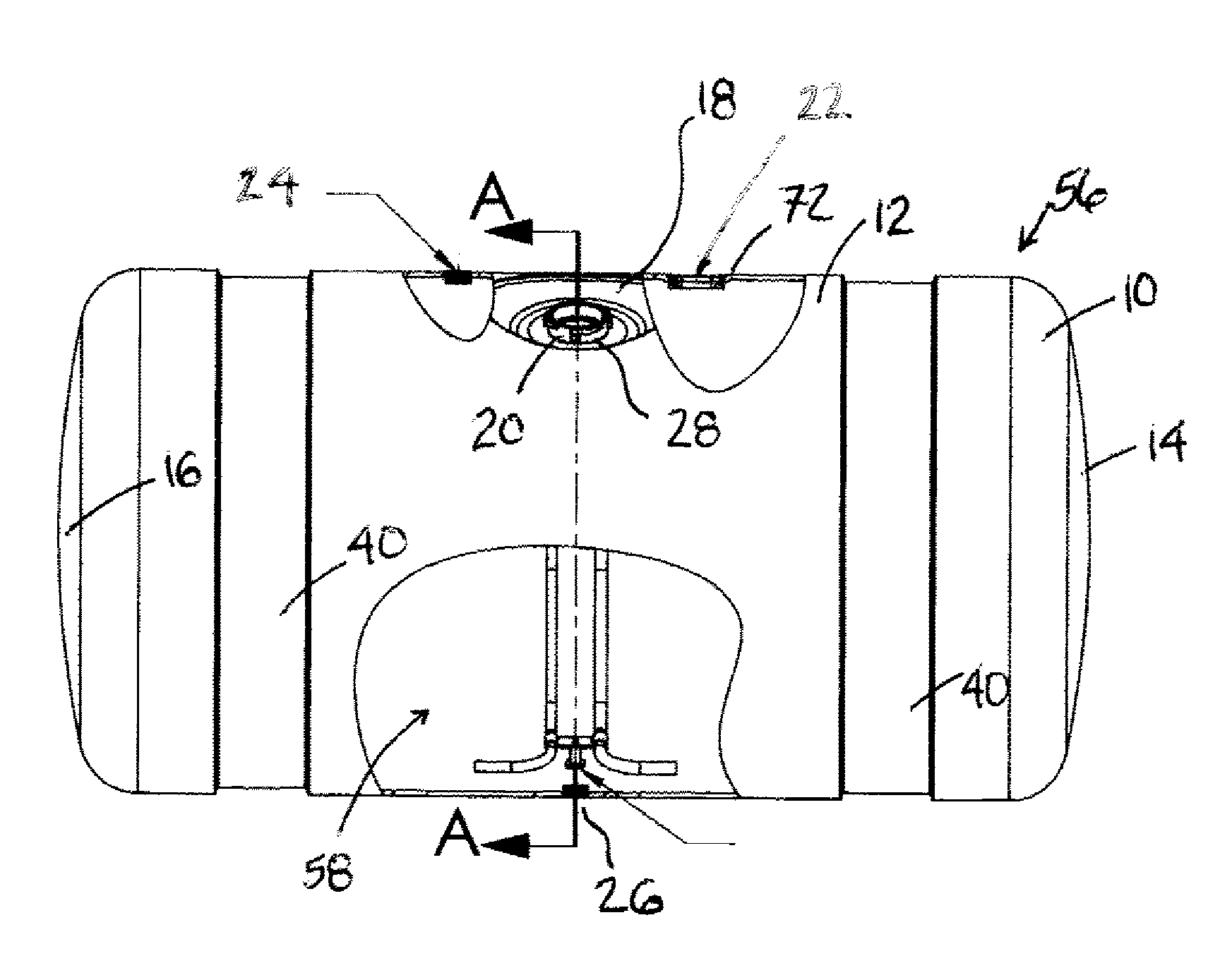
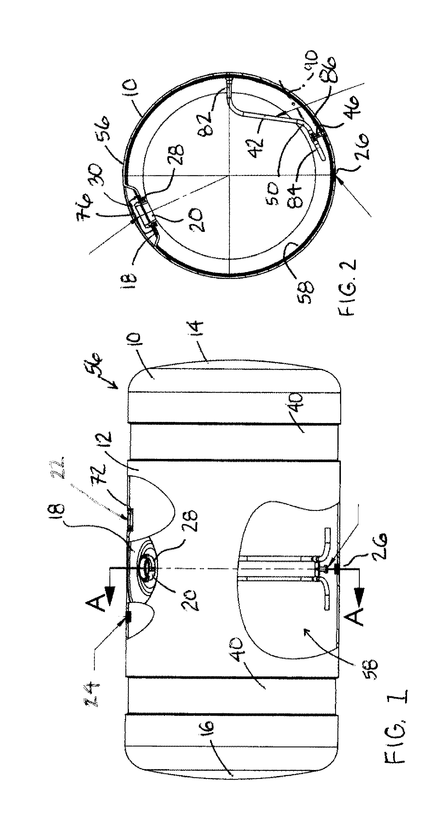
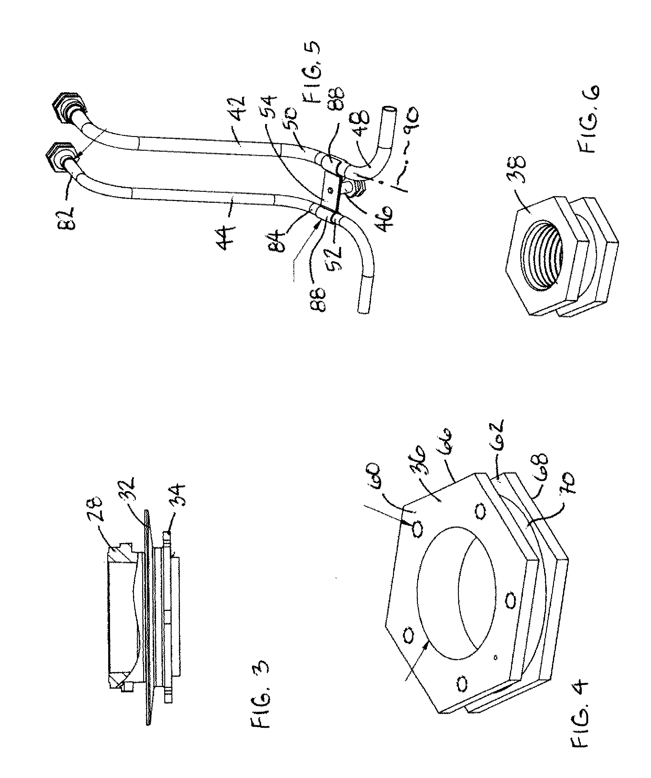
[0027]One embodiment of the present invention includes a process of molding a one-piece fuel tank that contains all the component fastening structures on the tank, i.e., molding the tank with previously formed metal component fastening structures already in place. The advantages of this method include fewer manufacturing process steps, fewer leak paths, reduced cost and, possibly, reduced weight of the manufactured fuel tank, larger fuel tank capacity for the space occupied by the tank, when compared with prior art metal welded fuel tanks. In another embodiment the method may include molding a fuel tank with the components molded integral with the fuel tank during formation of the fuel tank. The use of a rotational molding process may allow fabrication of a fuel tank with molded metal fitting ports manufactured integral with the tank and within the polymer, eliminating subsequent welding operations. A rotational molding process may also allow fabrication of the ...


PUM


Abstract

One embodiment of a molded fuel tank includes a fuel tank molded from a synthetic material, such as a composite polymer. One embodiment may include molding a fuel tank with metal component fastening structures positioned within the fuel tank as it is molded. One embodiment may include molding a fuel tank and integral component fastening structures simultaneously from synthetic materials. One embodiment of a molded fuel tank may include a fuel tank formed by a rotational molding process.

Description

[0001]This application claims the benefit of U.S. provisional patent application Ser. No. 61 / 632,759, filed on Jan. 30, 2012, in the name of Neal Keefer and Bruce Bosch.BACKGROUND OF THE INVENTION[0002]Truck fuel tanks typically are fabricated from multiple pieces of metal, such as steel or aluminum. The sheet of metal typically first is sheared to a rectangular shape, and then is punched or laser cut to form holes in the sheet. The sheet then is rolled into a cylinder, a “D” shape or a rectangular shape, and then welded along the longitudinal seam. The tank ends typically are formed from aluminum or steel sheets which are welded to the built-up, i.e., roiled shell. In a final step, fittings for fuel fill, fuel drain, fuel vent, fuel suction and fuel return tubes are welded into place on the shell or on the tank ends.[0003]This process has a number of challenges. One challenge occurs at the “T” weld joint, i.e., the location where the longitudinal seam and the circumferential seam h...

Claims


Application Information

Patent Timeline
IPC IPC(8): B64D37/02
CPCB64D37/02B60K2015/03493B60K2015/03447B60K15/03177B60K2015/0496B60K2015/03453B60K2015/0477B60Y2200/14B60K2015/047B60K2015/03039B65D39/084
Inventor KEEFER, NEALBOSCH, BRUCE
Owner KEEFER NEAL
Why Eureka
Try Eureka