Adjustable head-up display device

Active Publication Date: 2013-08-01
APTIV TECH LTD
View PDF5 Cites 39 Cited by
  • Summary
  • Abstract
  • Description
  • Claims
  • Application Information

AI Technical Summary

Benefits of technology

[0017]The projector preferably comprises a spatial light modulator (in English: “spatial light modulator”), e.g. a holographic memory, in which the information to be displayed is stored in the form of holograms, or a backlit liquid crystal display. In this case, the projector advantageously comprises a backlighting light source (e.g. a laser source or one or more luminescent diodes) arranged to send through the liquid crystal display a light beam not yet loaded with the information to be displayed, and in which the liquid crystal display is mounted displaceable transversally to the direction of the light beam. In accordance with a first modification, the light beam can remain immobile when the spatial light modulator is displaced. In accordance with another modification, the projector is configured displaceable in translation in its entirety. It will be noted that the translation of the spatial light modulator transversally to the direction of the beam permits adjustment of the transversal position of the virtual image relative to the axis: eyes of the driver—combiner. The device prefera

Problems solved by technology

Another problem is the adjustment of the head-up display device to the needs of the driver.
However, given that the strip acts as a lid, one of its sides remains exposed to t

Method used


Image

  • Adjustable head-up display device
  • Adjustable head-up display device
  • Adjustable head-up display device

Examples


Embodiment Construction

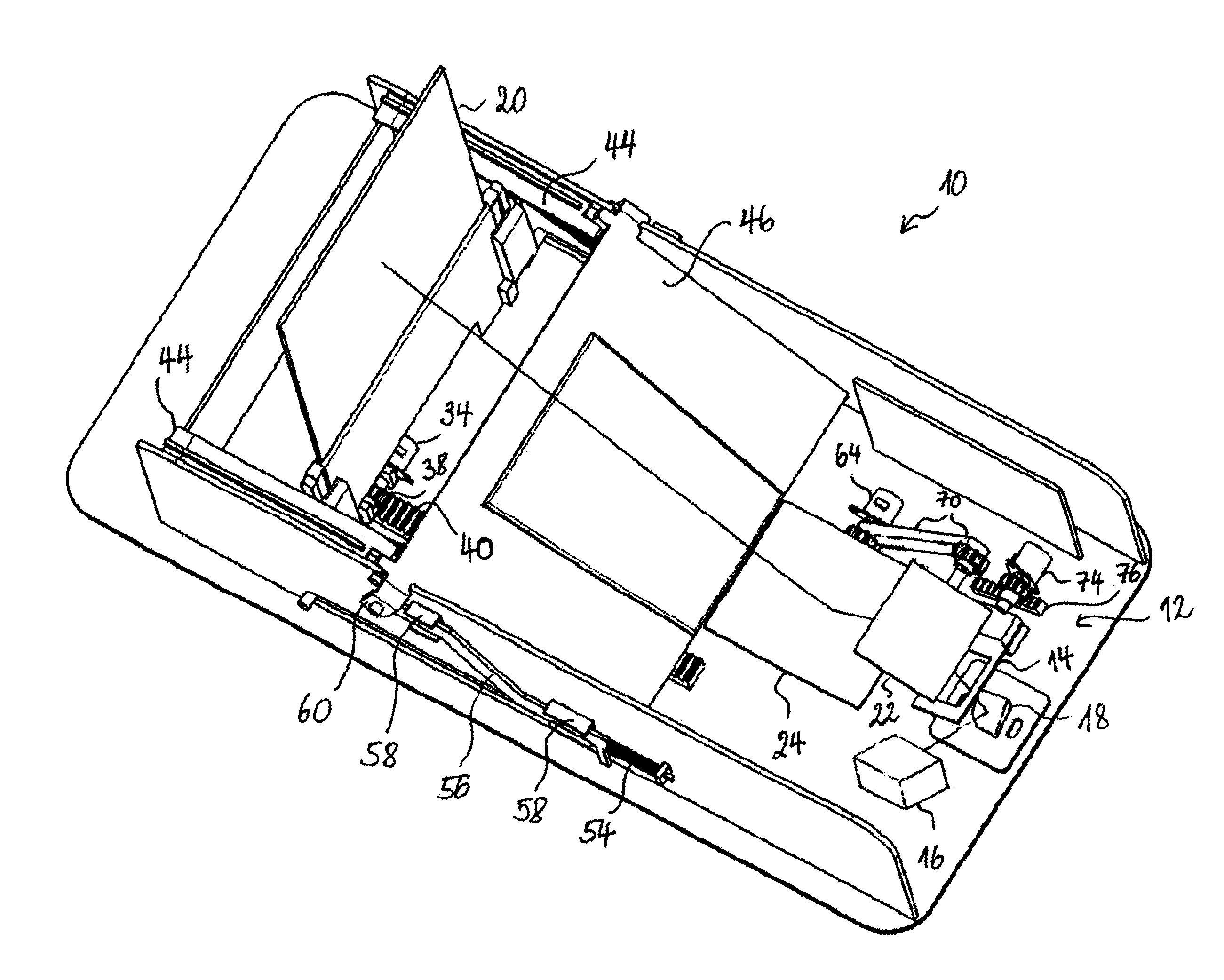
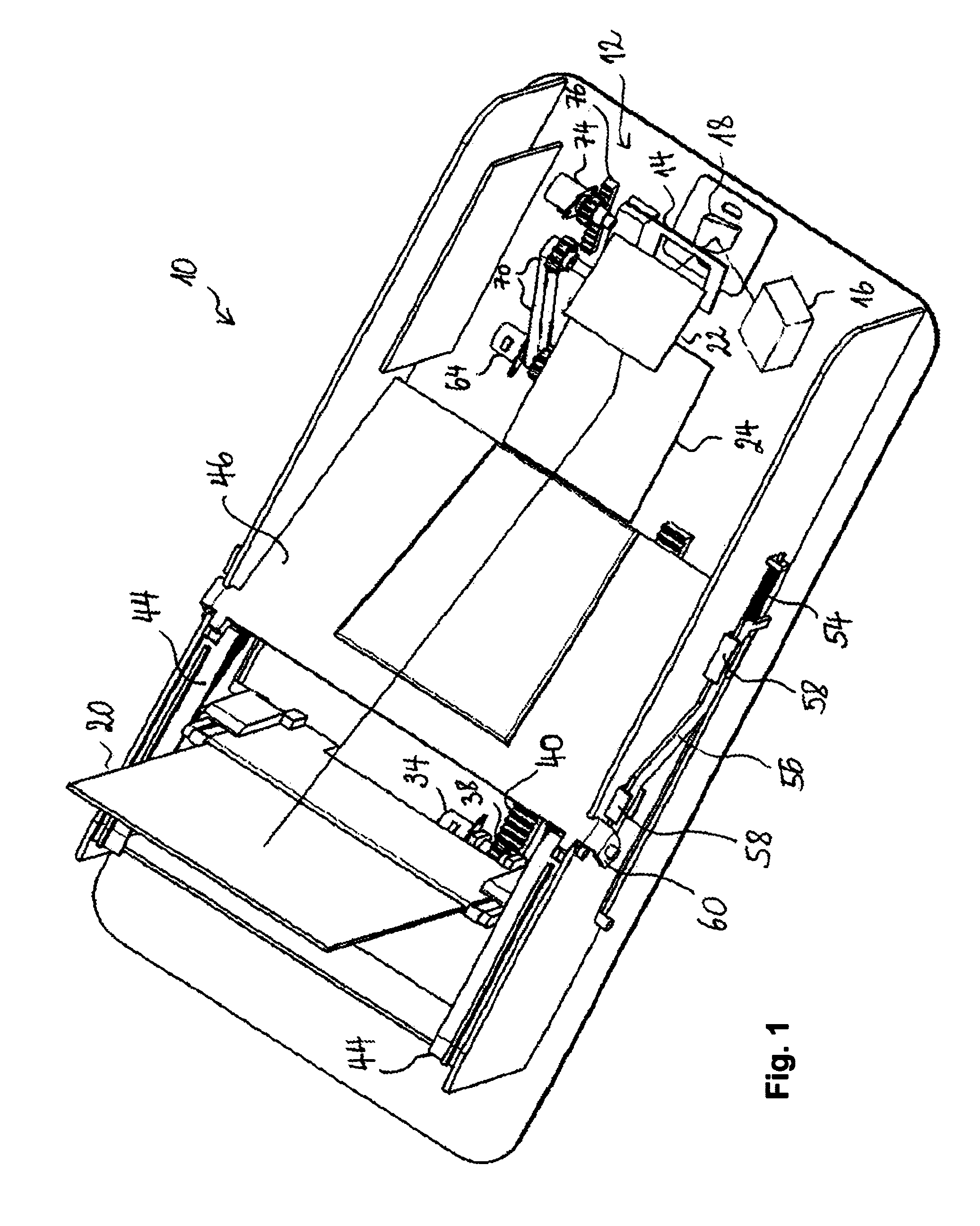
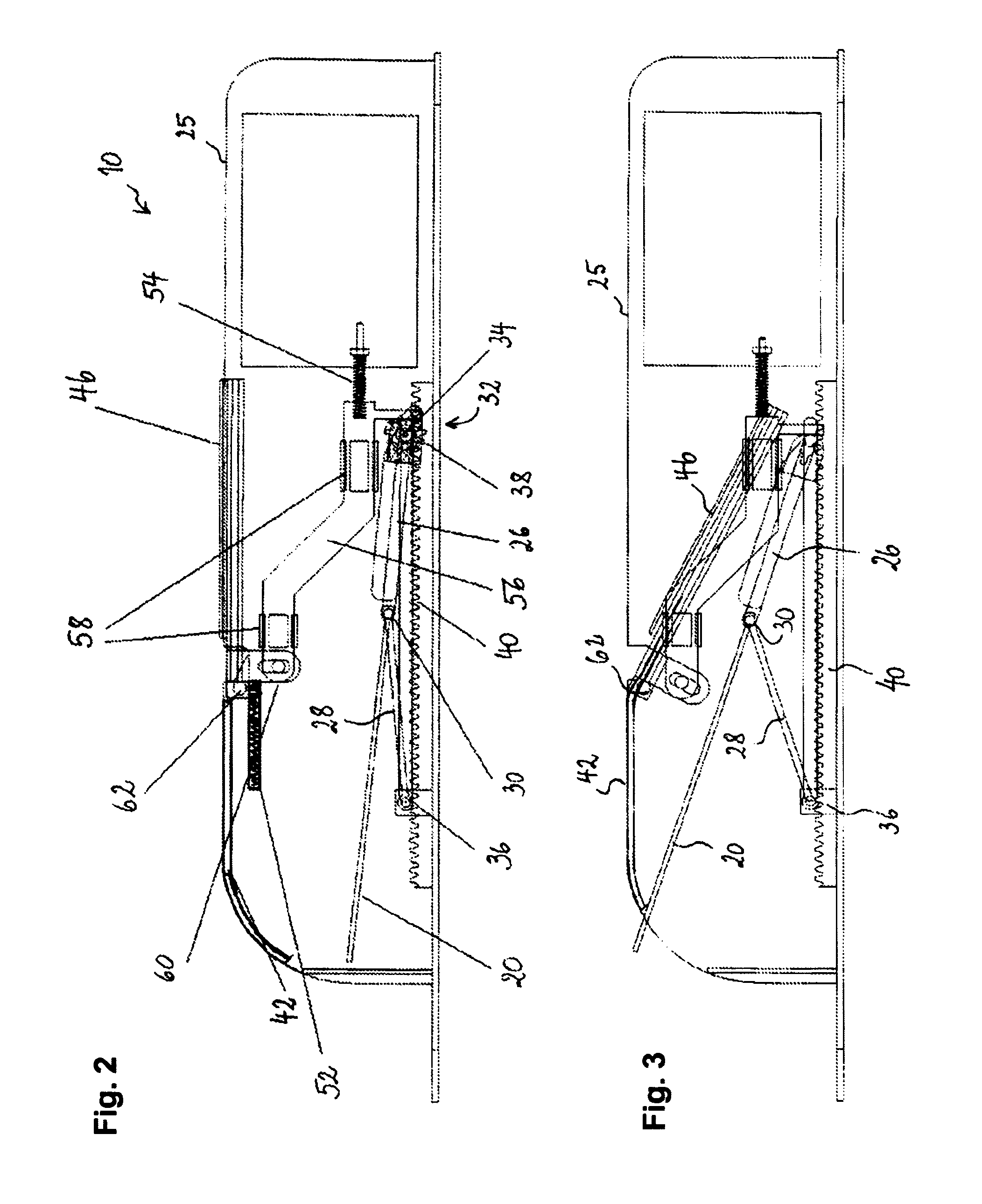
[0035]FIG. 1 shows a perspective view of a head-up display device 10 for a motor vehicle, in accordance with a preferred embodiment of the invention. The device 10 comprises a system for retraction of the combiner, described in more detail with reference to FIGS. 2 to 5, as well as a system for adjustment of the position of the virtual image, described in more detail below with reference to FIGS. 6 and 7.

[0036]The device 10 firstly comprises a projector 12 to generate the light beam loaded with the image representing the information to be displayed to the driver of the vehicle. The projector 12 includes a liquid crystal display 14, a light source 16 (coherent or non-coherent, depending on the type of the combiner, which can be diffractive or reflective producing a backlighting light beam and a mirror 18 returning the backlighting beam coming from the source 16 through the liquid crystal display 14. The liquid crystal display functions as a spatial light modulator and produces the im...


PUM


Abstract

The invention relates to a head-up display device, including a projector for generating a light beam carrying information to be displayed, a combiner having a display position for displaying the information in the field of vision of a user, and an optical system defining an optical path between the projector and the combiner when the latter is in the display position thereof, for directing the light beam onto the combiner. The optical system includes a first and a second deflecting mirror. The first mirror is arranged for receiving the light beam from the projector and for sending said light beam to the second mirror, the latter being arranged for sending the light beam over the optical path toward the combiner. An actuation system is provided for adjusting the length of the optical path between the projector and the combiner by positioning the first and second deflecting mirrors.

Description

CROSS-REFERENCE TO RELATED APPLICATION[0001]This application claims the benefit under 35 U.S.C. §371 of published PCT Patent Application Number PCT / EP 2011 / 061218, filed Jul. 4, 2011, claiming priority to French Patent Application Number FR1055779 filed on Jul. 16, 2010, and published as WO2012 / 007305 on Jan. 19, 2012, the entire contents of which is hereby incorporated by reference herein.TECHNICAL FIELD OF INVENTION[0002]The present invention relates to a head-up display device, in particular for motor vehicles, lorries, buses, trains, aircraft, etc. In particular, the invention relates to a head-up display device with a retractable combiner.BACKGROUND OF INVENTION[0003]A head-up display device typically includes a projection unit that produces a light beam intended to be directed towards a combiner in order to project images, in particular operating and driving information of a vehicle, in the form of a virtual image, in the field of view of a user, in particular a pilot or motor...

Claims


Application Information

Patent Timeline
IPC IPC(8): G02B27/01G02F1/13
CPCG02B7/1821G02B27/0149G02B27/01G02F1/1313G02B27/0101
Inventor MOUSSA, HASSANSIMON, CLAUDEGUIDI, ALAIN
Owner APTIV TECH LTD
Why Eureka
Try Eureka