Input/output interface circuit with overpower protection

a technology of input/output interface and protection, applied in the direction of vehicle position/course/altitude control, process and machine control, instruments, etc., can solve the problems of introducing measurement errors in input mode, relatively few output devices, damage to interface components,

Active Publication Date: 2013-08-01
JOHNSON CONTROLS TYCO IP HLDG LLP
View PDF3 Cites 1 Cited by
  • Summary
  • Abstract
  • Description
  • Claims
  • Application Information

AI Technical Summary

Benefits of technology

[0014]In accordance with yet another aspect, there is provided a method of selectively operating an input / output (I / O) interface circuit comprising a current source, an I / O node, and a measurement node between the current source and the I / O node in one of an input mode and an output mode, wherein the operating comprises: in the input mode: supplying electrical current from the current source to a variable-resistance input circuit through the I / O node; and measuring the resistance of the input circuit by measuring the voltage at the measurement node; and in the output mode: interposing a diode between the I / O node and the measurement node to prevent current from flowing from the I / O node to the measurement node; actuating an output circuit interconnected with the I / O node by selectively closing an output switch to form a conductive path from the output circuit to ground through the I / O node and the output switch.

Problems solved by technology

Possible alarm conditions include opening of doors, excessive temperatures, detection of motion, and the like.
Some systems may have a large number of sensor circuits, requiring a large number of input interfaces, but relatively few output devices.
Unfortunately, connection to an output circuit may cause damage to components of an interface.
Unfortunately, some techniques for isolating components in output mode may introduce measurement errors in input mode.
In addition, over-power conditions can cause damage to interface components.

Method used


Image

  • Input/output interface circuit with overpower protection
  • Input/output interface circuit with overpower protection
  • Input/output interface circuit with overpower protection

Examples


Embodiment Construction

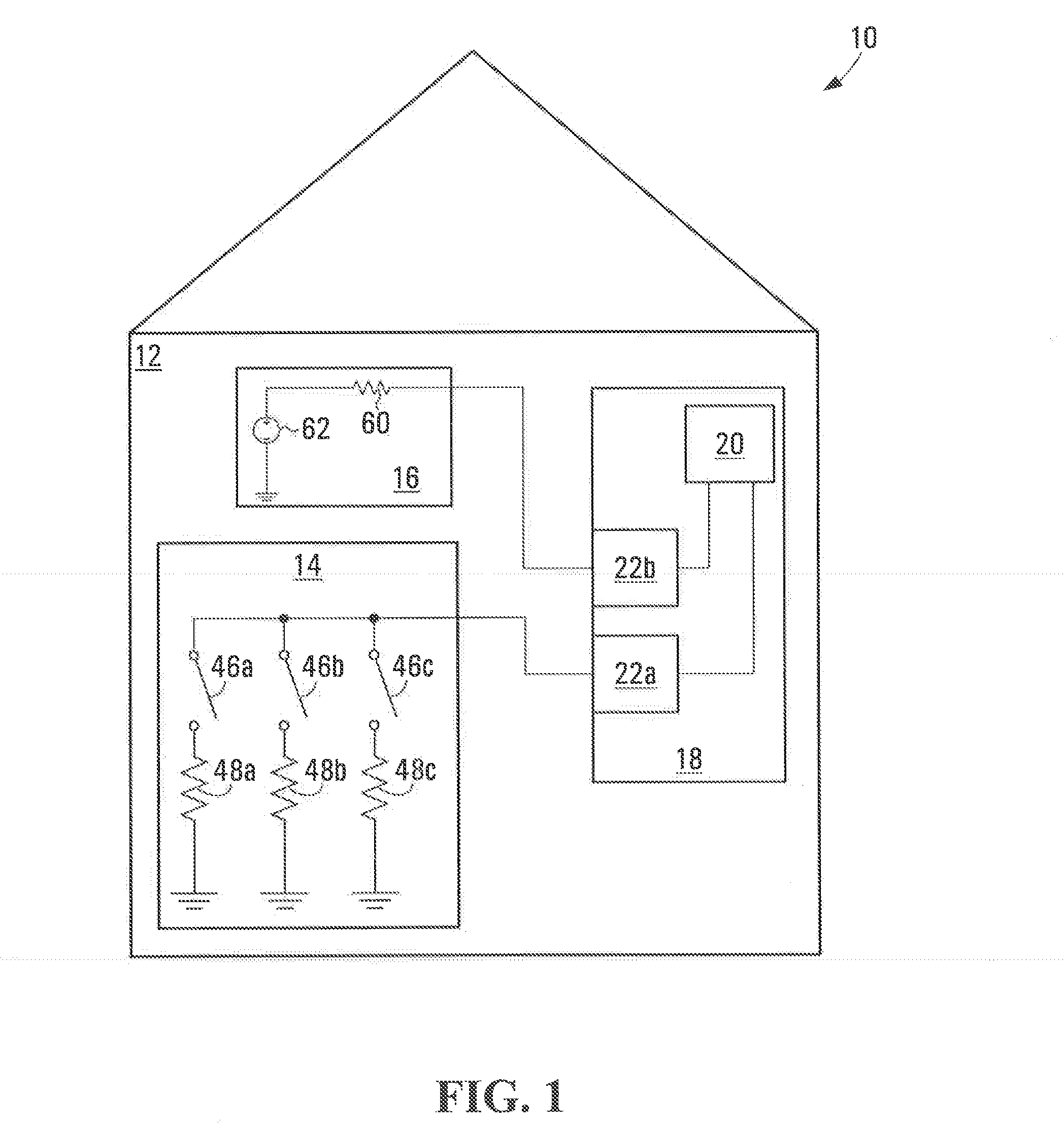
[0023]FIG. 1 depicts a security system 10, exemplary of an embodiment of the present invention. Security system 10 is installed at a premises 12 and includes a panel 18, interconnected with at least one input circuit, such as a sensor circuit 14 and an output circuit 16. Sensor circuit 14 and output circuit 16 are interconnected to panel 18, by way of input output (I / O) interface circuits 22a, 22b (individually and collectively, I / O interface circuits 22), exemplary of embodiments of the present invention.

[0024]Panel 18 further includes a processing unit 20, connected to I / O interface circuits 22. Processing unit 20 may be a conventional programmable controller or processor having multiple I / O pins each for receiving an analog input, or providing an analog or digital output to an interconnected I / O interface circuit 22. Processing unit 20 may include, or be associated with suitable combination of persistent and random access memory to allow processing unit to be programmed to operat...


PUM


Abstract

An interface circuit configurable in input and output modes comprises a current source; an input/output node; a diode to prevent current from flowing from the input/output node to the current source; a first switch to short-circuit the diode when closed; and a second switch to form a ground path from the input/output node when closed. In input mode, the first switch is closed and the state of a connected sensor circuit may be measured. In the output mode, the first switch is open, and the second switch may be closed to activate an output circuit. In the output mode, power dissipation may be monitored, and the diode may protect the current source and measurement node from current flowing through the output circuit. In the input mode, closing the first switch may prevent the diode from introducing measurement errors due to non-linear attenuation of perturbative AC signals.

Description

CROSS-REFERENCE TO RELATED APPLICATIONS[0001]The present application claims priority from U.S. Provisional Patent Application No. 61 / 591,368, filed Jan. 27, 2012, the contents of which are hereby incorporated by reference.FIELD OF THE INVENTION[0002]The present invention relates to input / output circuits, and particularly to security system input / output interfaces.BACKGROUND OF THE INVENTION[0003]Security systems typically include a control panel with input / output interface circuits for connection to one or more sensor circuits and one or more output circuits. Each sensor circuit may include a plurality of sensors, each to detect a different alarm condition. Possible alarm conditions include opening of doors, excessive temperatures, detection of motion, and the like. Each output circuit may include one or more output devices to be activated on the occurrence of certain conditions. Possible output devices may include lamps, relays, strobes and the like. Each sensor circuit is connecte...

Claims


Application Information

Patent Timeline
Patent Type & Authority Applications(United States)
IPC IPC(8): H02H3/08
CPCH02H3/08G05D1/00G08B25/00G08B25/04G08B25/14
Inventor BUCSA, ANDREICOJOCARU, AUREL
Owner JOHNSON CONTROLS TYCO IP HLDG LLP
Why Eureka
Try Eureka