

X-ray tube aperture body with shielded vacuum wall
a vacuum wall and aperture body technology, applied in the direction of x-ray tubes, x-ray tube cooling, x-ray tube vessel cooling, etc., can solve the problems of reducing generating excess heat, and damage to the affected component, so as to reduce the incidence of failure and increase the overall operating life of the x-ray tube
- Summary
- Abstract
- Description
- Claims
- Application Information
AI Technical Summary
Benefits of technology
Problems solved by technology
Method used
Image

Examples
Embodiment Construction
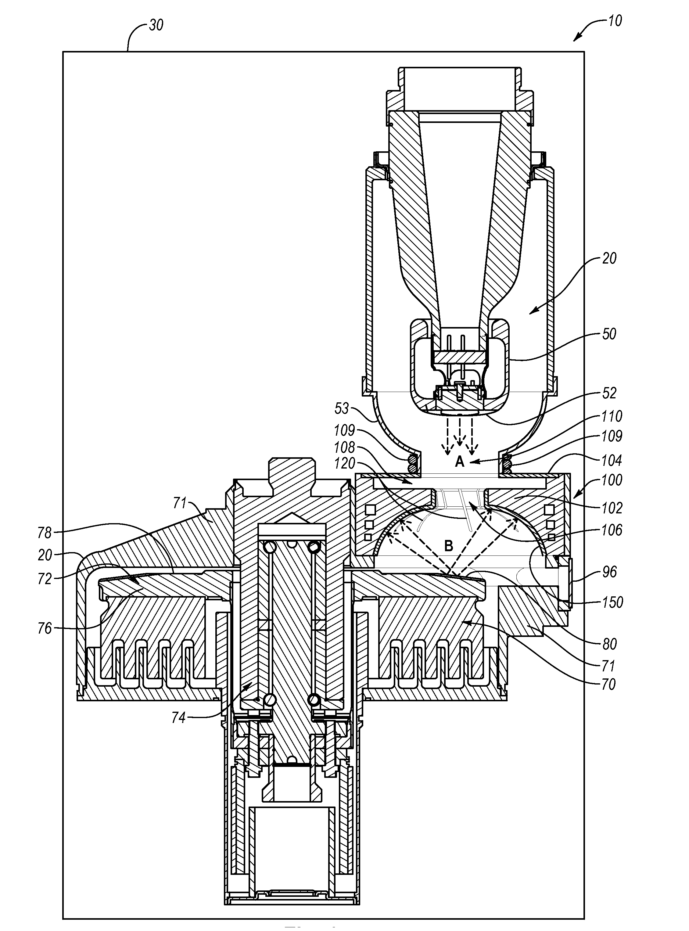
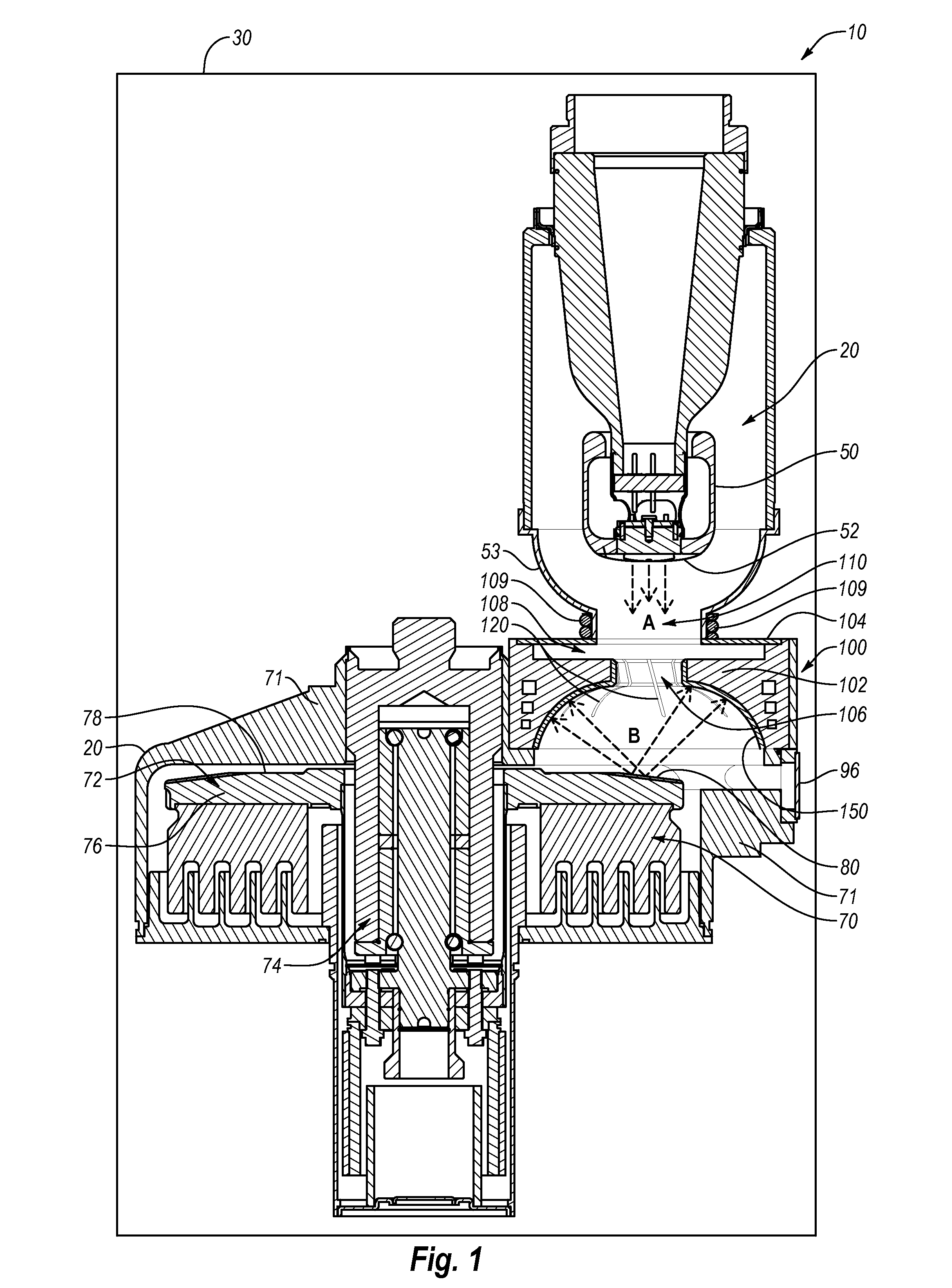
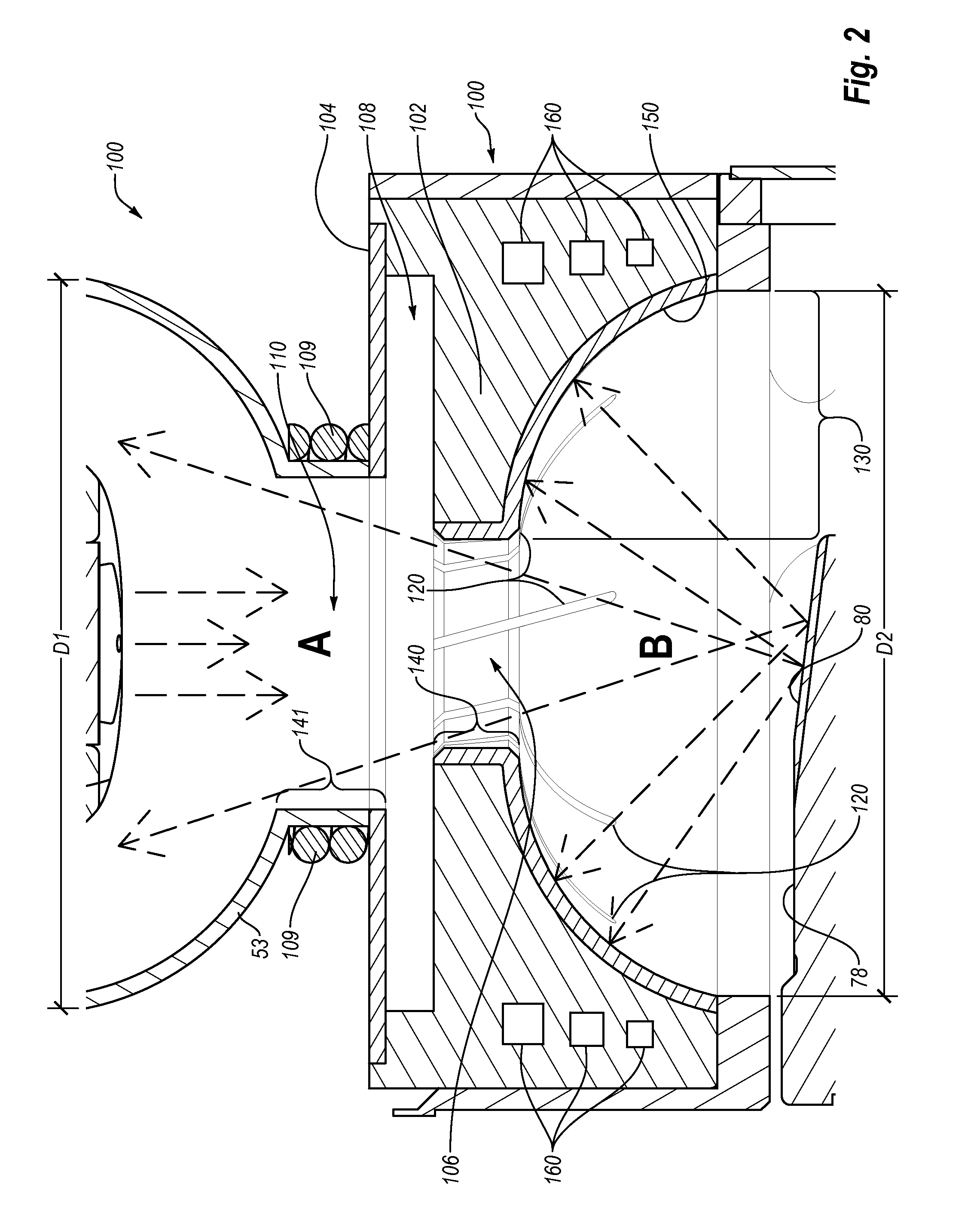
[0019]Reference will now be made to figures wherein like structures will be provided with like reference designations. It is understood that the drawings are diagrammatic and schematic representations of exemplary embodiments of the invention, and are not limiting of the present invention nor are they necessarily drawn to scale.
[0020]FIGS. 1-3 depict various features of example embodiments. In general, embodiments are generally directed to an aperture body for interposition between an electron emitter and an anode configured to receive the emitted electrons, such as in an x-ray tube. The aperture body includes an electron shield and a vacuum wall. The primary function of the electron shield is to “collect” electrons backscattered from the anode. Advantageously, the electron shield is configured to withstand the elevated temperatures produced by backscattered electrons and incident on selected portions of the electron shield and resultant thermal stresses that occur. The electron shi...
PUM
 Abstract
Description
Claims
Application Information