Image processing device, image processing method, program, and integrated circuit

Active Publication Date: 2013-08-01
SECURITY VIDEO CAMERA SYST INC
View PDF2 Cites 25 Cited by
  • Summary
  • Abstract
  • Description
  • Claims
  • Application Information

AI Technical Summary

Benefits of technology

[0016]The image processing device relating to the present invention contributes to specification of an area that is estimated to

Problems solved by technology

Actually, there is often the case where when the user checks a photographed ima

Method used


Image

  • Image processing device, image processing method, program, and integrated circuit
  • Image processing device, image processing method, program, and integrated circuit
  • Image processing device, image processing method, program, and integrated circuit

Examples


embodiment 1

Structure

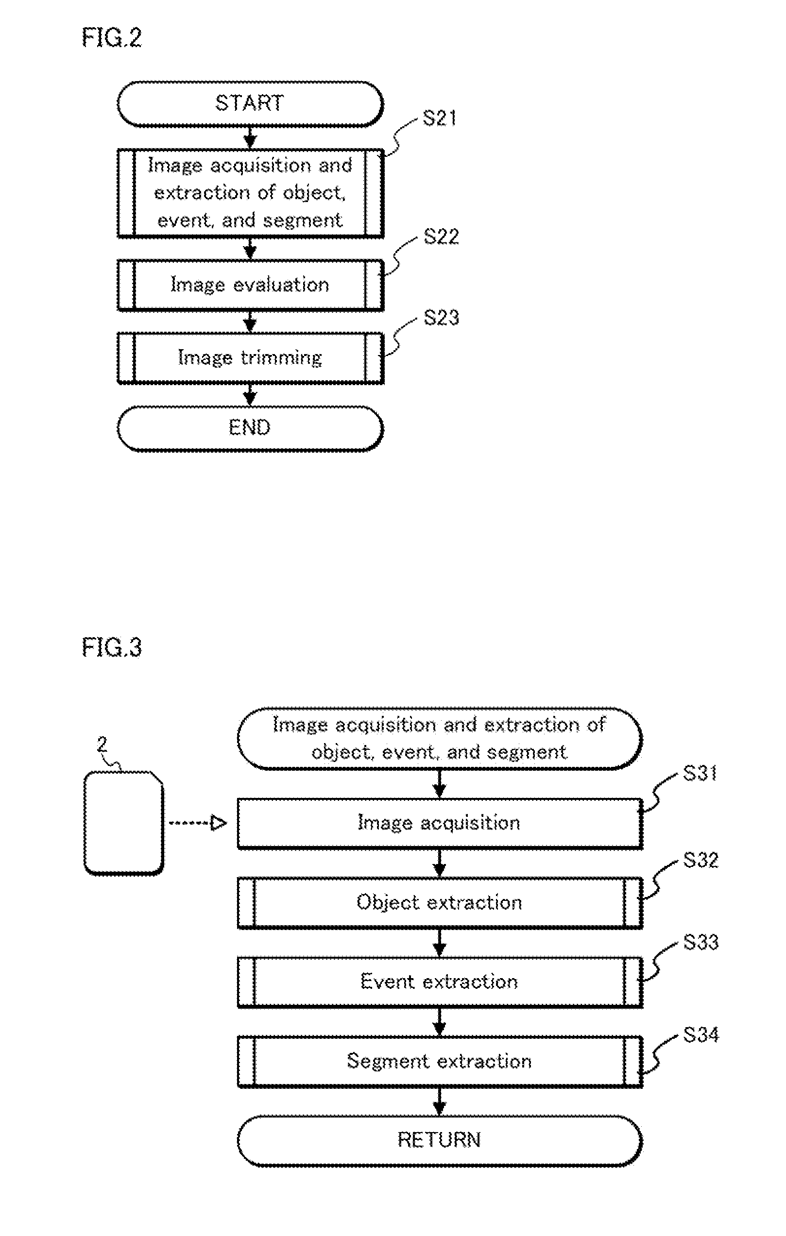
[0074]Embodiment 1 relates to an art of, with respect to an image group of images photographed by a user at an event such a travel, dividing each of the images into several segments, calculating an importance degree indicating evaluation for each of the segments based on a feature of the image and features of images anterior and posterior to the image, and cutting out an area from the image based on the calculated importance degree.

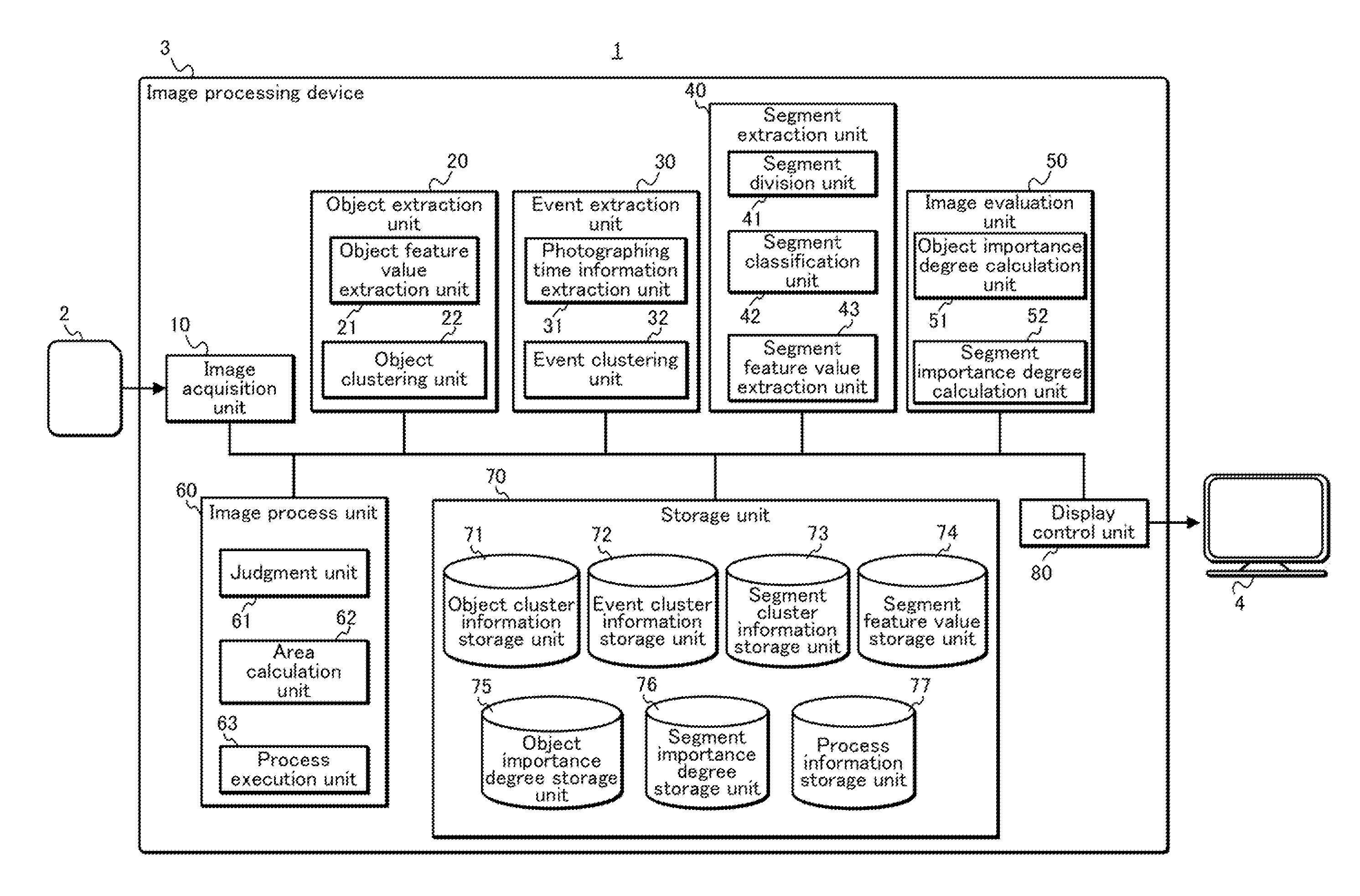
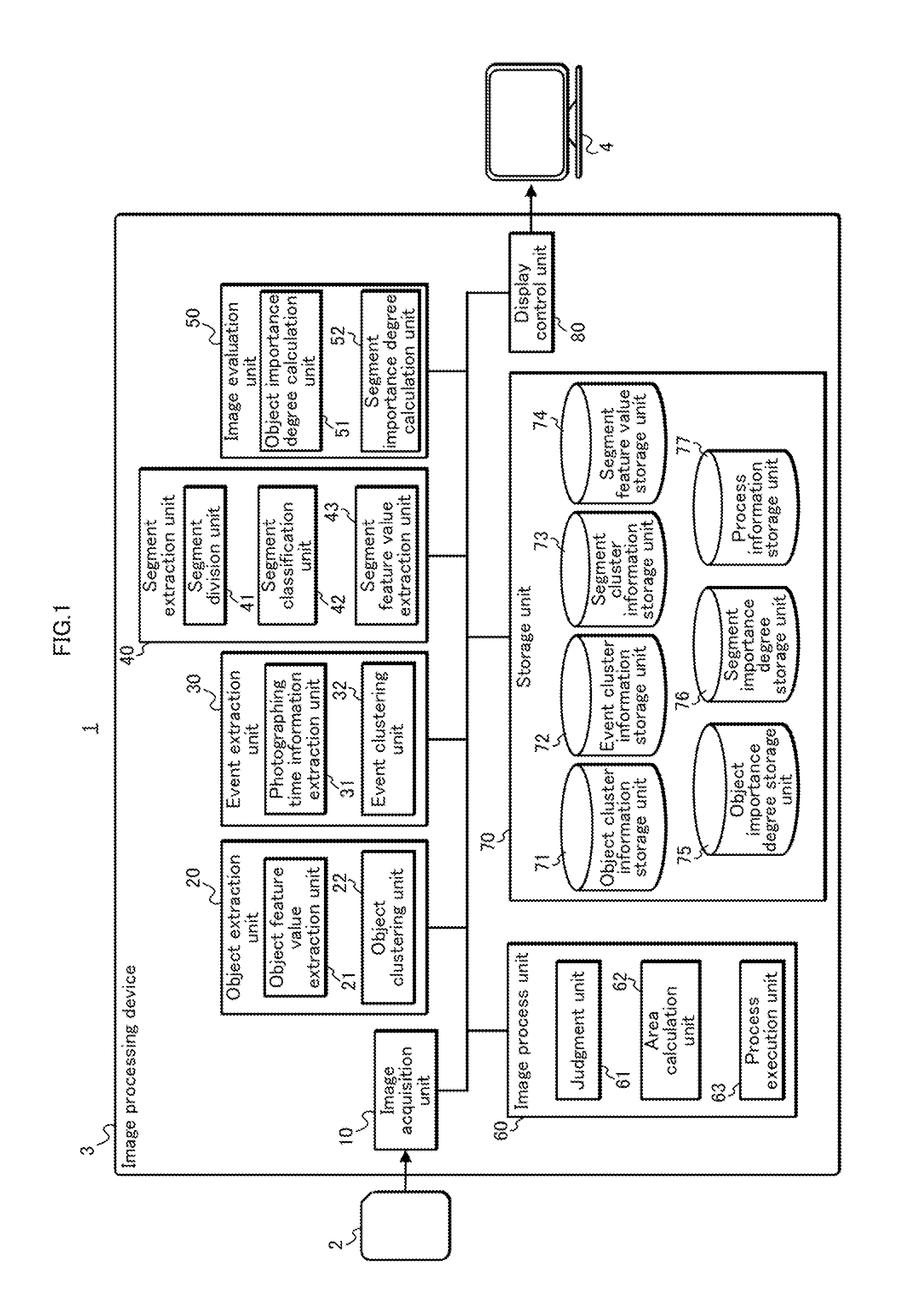
[0075]FIG. 1 is a block diagram showing the principal structure of an image processing system 1 relating to Embodiment 1.

[0076]The image processing system 1 includes a storage medium 2, an image processing device 3, and a display 4.

[0077]The image processing device 3 includes an image acquisition unit 10, an object extraction unit 20, an event extraction unit 30, a segment extraction unit 40, an image evaluation unit 50, an image process unit 60, a storage unit 70, and a display control unit 80. The object extraction unit 20 includes an object fe...

embodiment 2

[0194]In the present embodiment, an image is acquired from an image group shared on a network by a service such as an SNS (Social Network Service) and an image sharing service. This increases the number of images that are evaluation targets, thereby improving the reliability of evaluation results.

[0195]Assume the case where a user A has an extremely small number of images photographed by himself during a trip, for example. In this case, because of the extremely small number of images, even if the method described in Embodiment 1 is used, evaluation might not be made on an image including a background (landscape) and a foreground which are impressive for the user A (portion (a) of FIG. 39).

[0196]In view of this, evaluation is also made on images photographed and uploaded on a social network by a user B who is a friend of the user A (portion (b) of FIG. 39). This enables more appropriate evaluation on an image including a background (landscape) and a foreground which are impressive fo...

embodiment 3

[0218]In Embodiment 1, automatic trimming is performed without user operations. In the present embodiment compared with this, a trimming method with user operation is described.

[0219]As shown in FIG. 46, a higher weighting is given to an object designated by the user, such that the designated object is included in a trimming area.

[0220]FIG. 47 is a block diagram showing an image processing system 1b relating to Embodiment 3.

[0221]A user operation acquisition unit 93 included in an image processing device 3b acquires a user operation via an input interface or the like.

[0222]

[0223]FIG. 48 is a flowchart showing operations of trimming area calculation. Processing shown in FIG. 48 that are the same as those shown in FIG. 32 have the same step numbers as those in FIG. 32.

[0224]After acquisition of trimming information in Step S321 completes, the user operation acquisition unit 93 acquires a user operation (Step S481).

[0225]The user operation is acquired for example by displaying a menu c...


PUM


Abstract

Segments included in an image I are each classified as one of object (i.e., person) segments OS1 and OS2 and foreground segments FS1 and FS2. With respect to each of the foreground segments FS1 and FS2, an importance degree is calculated based on a composition of the image I and relations between the foreground segment of the image I and a foreground segment of an image other than the image I.

Description

TECHNICAL FIELD[0001]The present invention relates to an image processing device for specifying an area that is estimated to be important for a user among areas included in an image.BACKGROUND ART[0002]In recent years, an environment has been established where users can easily photograph images due to the popularization of digital cameras and the increase in capacity of storage media.[0003]Actually, there is often the case where when the user checks a photographed image afterwards, the user finds that an unnecessary part is included in the image. The user hopes to cut out only a necessary part from the image. Also, there is a case where when a user creates an album, the user needs to cut out a part from an image in accordance with the shape and the size of a frame of the album such that the image is placed within the frame.[0004]As an art relating to image cut-out, there has been an art of cutting out, from an image, a part including a face of a person or a part including the face a...

Claims


Application Information

Patent Timeline
IPC IPC(8): G06T7/00G06V10/26
CPCG06T7/0083G06T7/0048G06T7/0081G06T2207/10024G06T2207/20021G06K9/6223G06T2207/30201H04N1/3876G06K9/3241G06K9/34G06T2207/20144G06T7/77G06T7/11G06T7/194G06V10/255G06V10/26G06V10/763G06F18/23213
Inventor YABU, HIROSHI
Owner SECURITY VIDEO CAMERA SYST INC
Why Eureka
Try Eureka