Linear Guide Apparatus

a bearing and linear technology, applied in the direction of bearings, bearings, shafts and bearings, etc., can solve the problems of deformation of the flexible sliding member, and deformation of the dust-proof performance, so as to reduce the wear resistance and breakage strength, reduce the cost of production of the third lip, and improve the dust-proof performance. a long time.

Active Publication Date: 2013-08-01
NSK LTD
View PDF3 Cites 13 Cited by
  • Summary
  • Abstract
  • Description
  • Claims
  • Application Information

AI Technical Summary

Benefits of technology

[0028]According to the linear guide apparatus of the present invention, the side seal unit comprises a first seal member, at the slider side, arranged along the axial direction of the slider, a second seal member at an outside of the slider in the axial direction, and a lubricating member held between the first seal member and the second seal member, and the first seal member comprises first lip parts sliding against the rolling element rolling grooves of the guide rail, the second seal member comprises second lip parts sliding against the rolling element rolling grooves of the guide rail, the lubricating member comprises a first oil-containing member for supplying lubricant to the rolling element rolling grooves of the guide rail. Therefore, the lubricant is supplied to both of the first lip parts and the second lip parts sliding against the rolling element rolling grooves. Accordingly, it is possible to maintain the first lip parts and the second lip parts in a state of little wear over a long period of time, without insufficient lubrication at the first lip parts of the first seal member and the second lip parts of the second seal member, The can be maintained.
[0029]Further, the first lip parts and the first oil-containing member are arranged not to come into contact with each other, and the second lip parts and the first oil-containing member are arranged not to come into contact with each other, so that the pressing forces of the first lip parts and the second lip parts against the rolling element rolling grooves will never degrade. It is therefore possible to maintain a high z dust-proof performance over a long period of time.
[0030]Further, in this linear guide apparatus, when the first seal member comprises a first seal plate having the first lip parts and a first holding plate for holding the first seal plate, the second seal member comprises a second seal plate having the second lip parts and a second holding plate for holding the second seal plate, the lubricating member comprises the first oil-containing member and a case for holding the first oil-containing member, the case is used to avoid mutual contact between the first lip parts and the first oil-containing member, and the second holding plate is used to avoid mutual contact between the second lip parts and the first oil-containing member, it is possible to avoid mutual contact of the first lip parts and first oil-containing member and mutual contact of the second lip parts and first oil-containing member with certainty.
[0031]Furthermore, in this linear guide apparatus, when an auxiliary side seal is provided between the side seal unit and an axial direction end part of the slider, and the auxiliary side seal comprises third lip parts sliding against the rolling element rolling grooves of the guide rail, even if the dust-proof performance of the side seal unit degrades along with a long-term vehicle operation, it is possible to maintain the overall dust-proof performance with the auxiliary side seal.
[0032]Further, in this linear guide apparatus, when the breakage strength of the third lip parts is smaller than those of the first lip parts, and is smaller than those of the second lip parts, it is possible to inexpensively produce the third lip parts of the auxiliary side seal. The third lip parts are positioned at the inner side in the axial direction of the slider (slider side) more than the first lip parts and second lip parts. Thus, it is difficult for foreign matters to enter the third lip parts from the outside. Therefore, the third lip parts may have a wear resistance and breakage strength smaller than those of the first lip parts and second lip parts.
[0033]Furthermore, in this linear guide apparatus, when an auxiliary lubricating member is provided between the auxiliary side seal and an axial direction end part of the slider, and the auxiliary lubricating member comprises a second oil-containing member for supplying lubricant to the rolling element rolling grooves of the guide rail, the lubricant is supplied from the second oil-containing member of the auxiliary lubricating member to the rolling element rolling grooves of the guide rail. As a result, the lubricant is supplied to the third lip parts of the auxiliary side seal sliding against the rolling element rolling grooves. Accordingly, the third lip parts of the auxiliary side seal are maintained in a state of little wear over a long period of time. Therefore, even if the dust-proof performance of the side seal unit degrades along with long vehicle operation, it is possible to maintain the dust-proof performance with the dust-proof performance of the auxiliary side seal.

Problems solved by technology

However, in the linear guide apparatus shown in FIG. 15 and the linear guide apparatus shown in FIG. 16, there are the following problems.
Accordingly, the lip parts of the hard seal members 117 arranged at the outermost side are insufficiently lubricated, the lip parts become worn, and the dust-proof performance degrades.
Accordingly, there is a problem that the dust-proof performance in the flexible sliding member 212 degrades.

Method used


Image

  • Linear Guide Apparatus
  • Linear Guide Apparatus
  • Linear Guide Apparatus

Examples


first embodiment

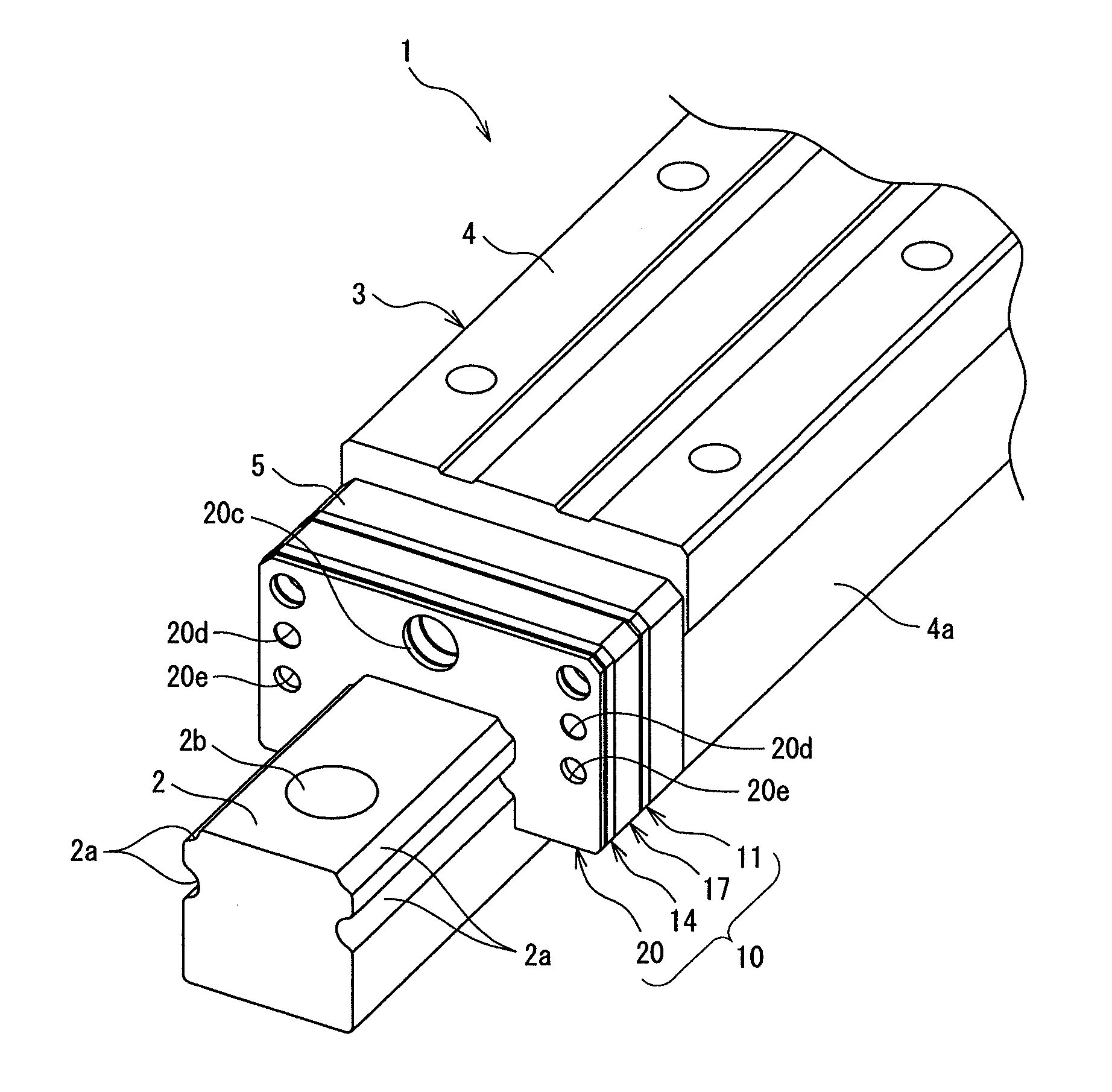
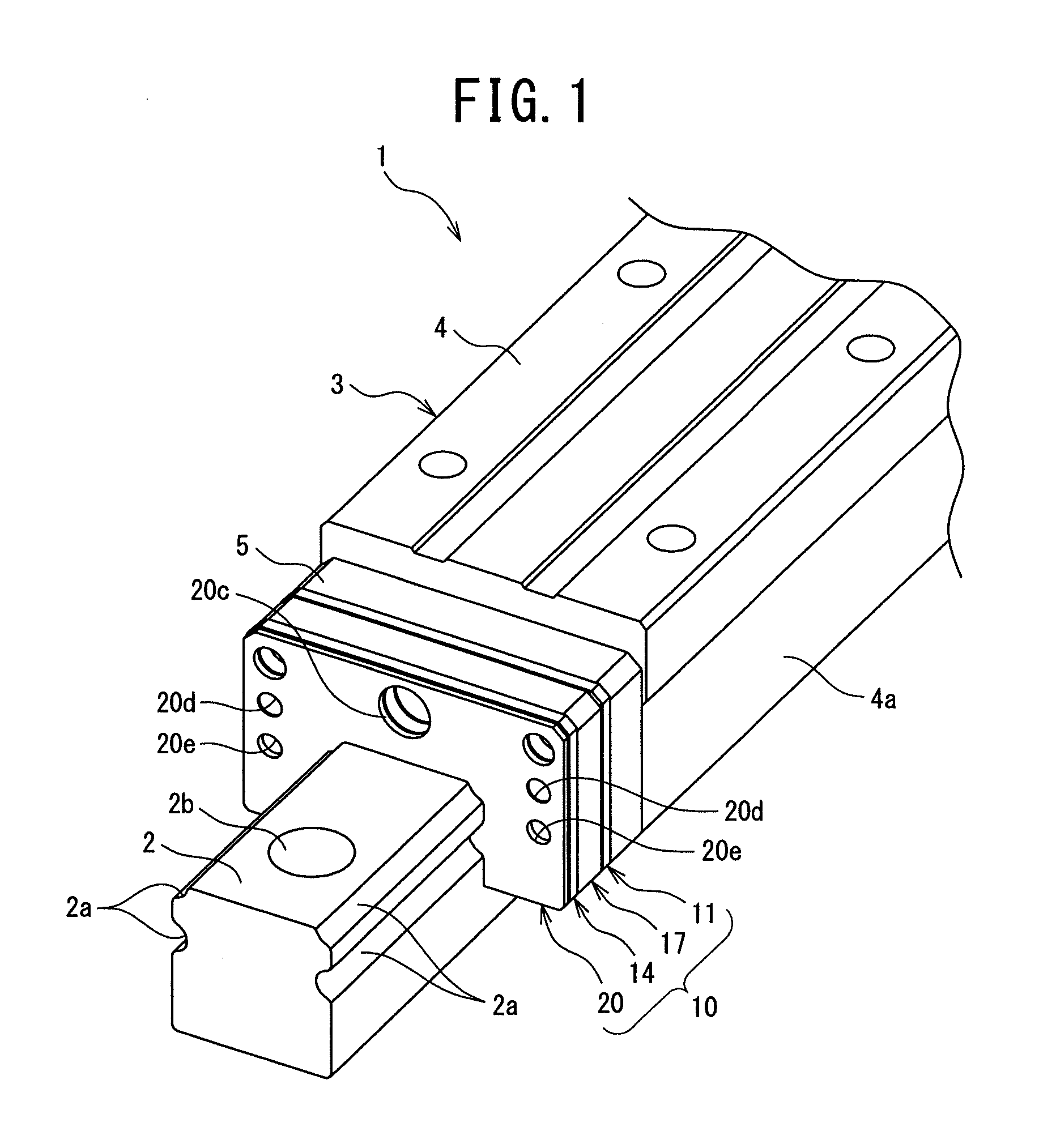
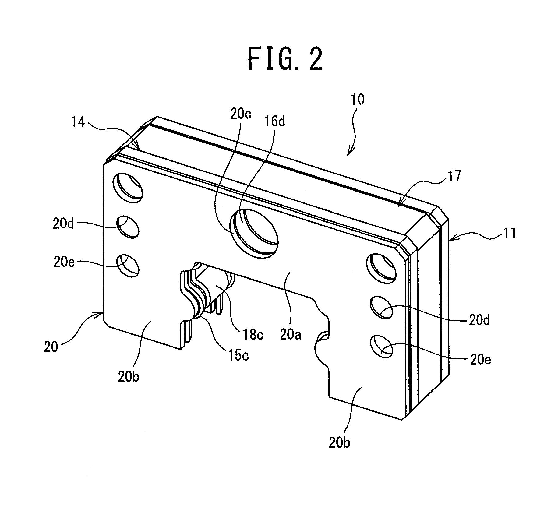
[0051]FIG. 1 is a perspective view showing a linear guide apparatus according to the present invention. FIG. 2 is a perspective view of a side seal unit used for the linear guide apparatus shown in FIG. 1. FIG. 3 is a disassembled perspective view of the side seal unit shown in FIG. 2. FIG. 4 is a disassembled perspective view of a first seal member used in the side seal unit shown in FIG. 2. FIG. 5 is a disassembled perspective view of a lubricating member used in the side seal unit shown in FIG. 2. FIG. 6 is a cross-sectional schematic view of the vicinity of the side seal unit of the linear guide apparatus shown in FIG. 1. FIG. 7 is a cross-sectional schematic view for explaining the action of the side seal unit in the linear guide apparatus shown in FIG. 1. FIG. 8 is a cross-sectional schematic view for explaining the action of the side seal unit in the linear guide apparatus shown in FIG. 1.

[0052]The linear guide apparatus 1 shown in FIG. 1 is provided with: a guide rail 2 whic...

second embodiment

[0083]The linear guide apparatus 1 shown in FIG. 12 and FIG. 13 has a basic configuration similar to that of the linear guide apparatus 1 shown in FIG. 9 to FIG. 11, but differs from the linear guide apparatus 1 shown in FIG. 9 to FIG. 11 in that an auxiliary lubricating member 50 is provided between the auxiliary side seal 30 and the axial direction end part of the slider 3 (actually, the end cap 5).

[0084]Here, the auxiliary lubricating member 50, as shown in FIG. 12 and FIG. 13, is provided with: a second oil-containing member 51; and a case 52 for accommodating the second oil-containing member 51. The second oil-containing member 51 is provided with: a base part 51a formed to have a substantially U-shaped cross-section so as to straddle the guide rail 2 and extending in the direction traversing the guide rail 2; and a pair of dangling parts 51b extending from both ends of the base part 51a in the direction traversing the rail downward along the two side surfaces of the guide rai...


PUM

PropertyMeasurementUnit
thicknessaaaaaaaaaa
breakage strengthaaaaaaaaaa
hardnessaaaaaaaaaa

Abstract

A linear guide apparatus maintaining a high dust-proof performance over an extended period of time and includes side seal units attached to end parts of a slider in the axial direction. Each side seal unit is provided with: a first seal member, at the slider, arranged in the axial direction of the slider; a second seal member at the outside of the slider in the axial direction; and a lubricating member held between the first and second seal members. The first seal member has first lip parts sliding against the rolling element rolling grooves of the guide rail, while the second seal member has second lip parts sliding against the rolling element rolling grooves. The lubricating member has a first oil-containing member for supplying lubricant to the rolling element rolling grooves. The first and second lip parts are arranged not to come into contact with the first oil-containing member.

Description

TECHNICAL FIELD[0001]The present invention relates to a linear guide bearing apparatus (linear guide apparatus) suitable for use in, for example, a machine apparatus like a machine tool where cutting dust or other foreign matter is produced in the surroundings.BACKGROUND ART[0002]As a conventional general linear guide apparatus, for example, the one shown in FIG. 14 is known.[0003]The linear guide apparatus shown in FIG. 14 is provided with a guide rail 101 which extends in the axial direction and a slider 102 which straddles the guide rail 101 capable of moving relatively in the axial direction.[0004]The two side surfaces of the guide rail 101 are formed with rolling element rolling grooves 103 which extend in the axial direction. The slider body 102A of the slider 102 is formed at the inner surfaces of two sleeve parts 104 with rolling element rolling grooves 107 which face the rolling element rolling grooves 103. Further, between each two facing rolling element rolling grooves 10...

Claims


Application Information

Patent Timeline
Patent Type & Authority Applications(United States)
IPC IPC(8): F16C29/04F16C33/66F16C33/76
CPCF16C29/086F16C33/6648F16C29/0642F16C33/66F16C33/76F16C29/04F16C29/0647F16C2322/39
Inventor MATSUMOTO, JUNSATO, RYOICHIHATTORI, MASARU
Owner NSK LTD
Why Eureka
Try Eureka