

Production of Paraxylene
a technology of paraxylene and isomerization, which is applied in the field of xylene isomerization, can solve the problems of large start-up exotherm, extreme bed temperature excursion, and excess heat of reaction, and achieve the effect of reducing the loss of xylene and avoiding the negative consequences of high exotherm
- Summary
- Abstract
- Description
- Claims
- Application Information
AI Technical Summary
Benefits of technology
Problems solved by technology
Method used
Image

Examples
example 1
[0053]The experiments were carried out in a pilot plant scale fixed bed unit. The reactor has a catalyst basket with 0.64″ ID and 17.5″ length. The basket was loaded with xylene isomerization catalyst extrudates. The top bed is 1 / 20″ quadrolobe shaped extrudates which contain Re supported on said solid extrudates composed of ZSM-5 molecular sieve and a binder. The bottom bed is 1 / 16″ cylindrical extrudates which contain Re on said solid extrudates composed of ZSM-5 molecular sieve and a binder. The dual-bed catalysts were packed in the reactor basket with a 35 / 65 bed ratio, by weight (first catalyst: second catalyst). The total fresh catalyst loading was 15.5 g. The reactor voids were filled with inert glass beads, and 80 / 120 mesh quartz sand was used to fill catalyst bed interstitial spaces. These measures were taken to minimize channeling of the reactant gas flow. The reactor is equipped with a thermal well (⅛″OD), to allow a traveling thermocouple to record the catalyst temperatu...
example 2
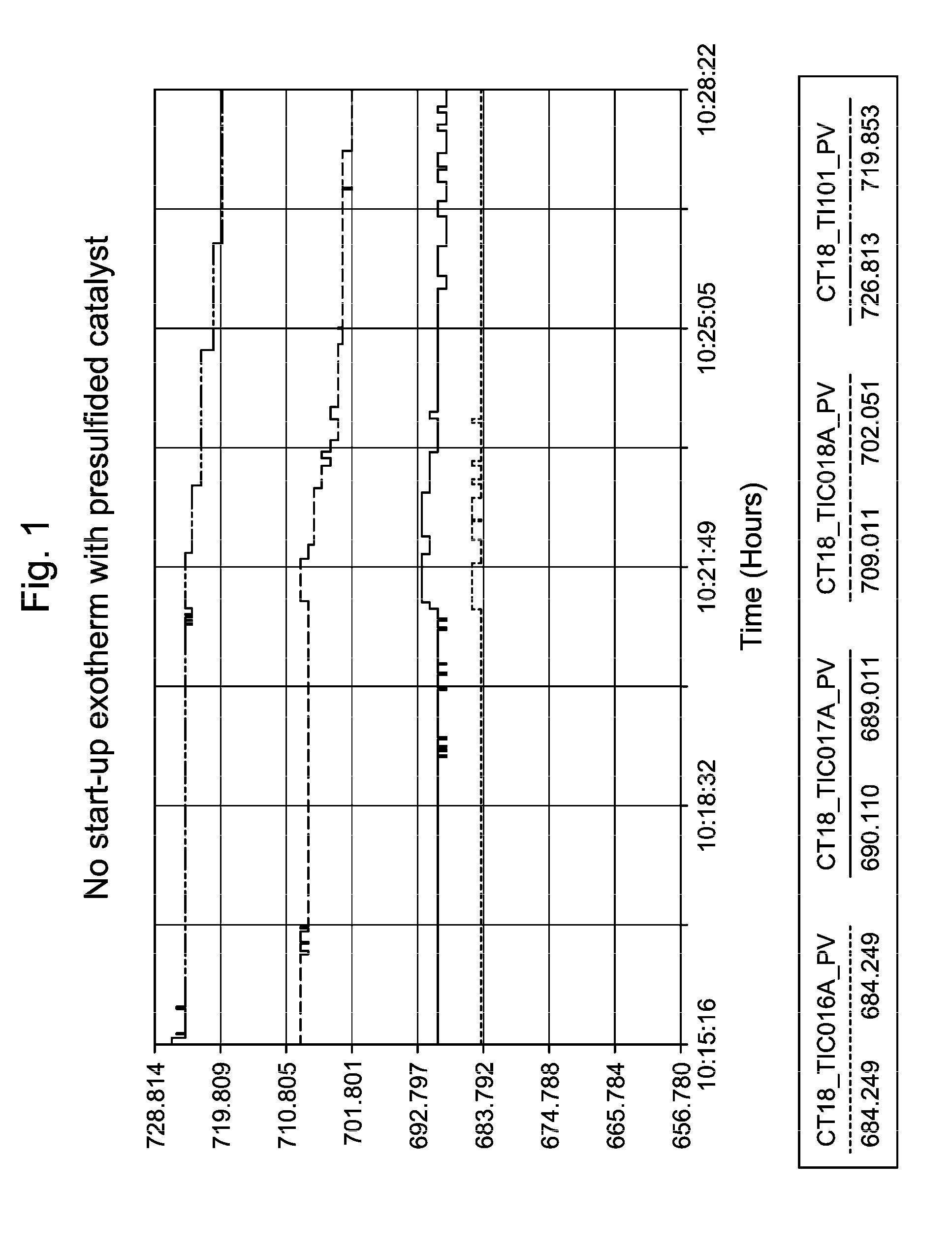
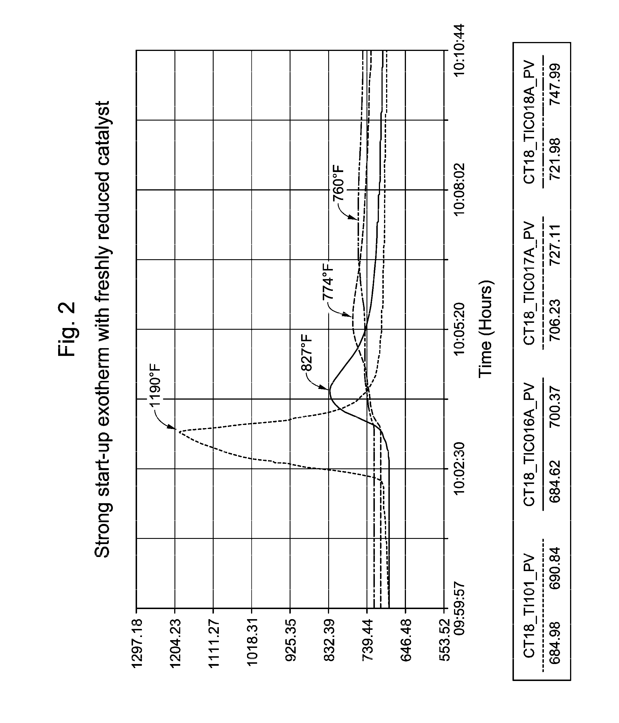
[0060]In commercial unit A, the presulfiding method according to the invention was implemented. The sulfiding agent used was dimethyl-disulfide (DMDS) liquid. The injection facilities consisted of a storage barrel of DMDS on a weight scale, two positive displacement pumps, and associated stainless steel tubing. Pre-sulfiding of the fresh xylene isomerization catalyst started immediately following completion of the catalyst dry-out. The catalyst bed was maintained at an elevated temperature of 359° C.
[0061]DMDS decomposed to H2S and CH4 once it was injected into the reactor. The DMDS injection rates were set to give 500 vppm (sometime termed ppmV, or parts per million by volume) H2S at the reactor inlet. The recycle gas was monitored for H2S breakthrough via Draeger tubes. The total sulfur injected corresponded to 1 equivalent of catalyst metal content. Breakthrough of H2S (>100 vppm in recycle gas) was detected during this commercial catalyst presulfiding application. No temperature...
example 3
Commercial Unit B
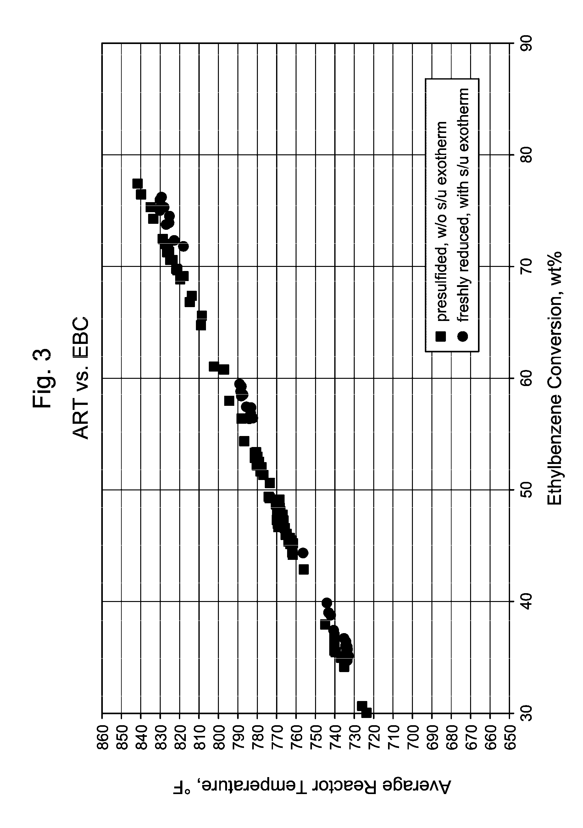
[0064]In commercial unit B, independent DMDS injection facilities were used to introduce sulfur to two parallel reactors simultaneously as soon as the catalyst dry-out and reduction processes were completed. The presulfiding was conducted at the reactor temperature of 360° C., and the inlet pressure of 1.3 MPa. The DMDS injection rates were set to give 500 vppm H2S concentration at the reactor inlet. Recycle gas H2S concentration was monitored frequently during the presulfiding process. Hydrocarbon feed introduction started immediately after the 2X sulfur equivalents (based on metal atom content) were injected. No H2S breakthrough was detected in the recycle gas. Without wishing to be bound by theory, it is believed that the large metal surface area of the reactors and the feed / effluent heat exchangers had adsorped additional sulfur.
[0065]The initial feed rate was at 28% of the design. Low WHSV relative to design gives high H2 / HC at constant recyle gas rate. Both ty...
PUM
| Property | Measurement | Unit |
|---|---|---|
| temperature | aaaaa | aaaaa |
| temperature | aaaaa | aaaaa |
| surface to volume ratio | aaaaa | aaaaa |
Abstract
Description
Claims
Application Information