Systems and methods for creating a near optimal maintenance plan

a maintenance plan and system technology, applied in the field of computerized systems and maintenance plan optimization, can solve the problems of lack of reasonable routine maintenance or repair, man has yet to invent a useful machine or a vehicle that can function, and shorten the useful life of any ass

Inactive Publication Date: 2013-08-01
HONEYWELL INT INC
View PDF3 Cites 19 Cited by
  • Summary
  • Abstract
  • Description
  • Claims
  • Application Information

AI Technical Summary

Problems solved by technology

Man has yet to invent a useful machine or a vehicle that can function throughout its designed useful life without some kind of maintenance or repair being performed.
In fact, the lack of reasonable routine maintenance or repair will shorten the useful life of any asset, particularly for complex systems such as aircraft and manufacturing systems.
Each isolation procedure and each related repair procedure have an estimated execution time cost and a material cost necessary to complete the isolation procedure or the repair procedure.
With complex systems, such as aircraft, a casualty may have a number of potential FM's that could be the underlying cause of the casualty.
This means that when parts with a short wait-time are mixed with parts that have a long wait-time in the same order, the longer wait time parts will delay the parts that could be available earlier.
There may also be a return penalty for parts that are ordered and not used.
As such, the maintenance planning problem and the parts order scheduling problem are mixed and cannot be solved independently as in a traditional setting.
However, the same sequence of operations may not be optimal if different parts have different wait-times.
However, the conventional way is not always the best in practice.
However, the time required for executing an exhaustive search increases exponentially with the number of FMs in the ambiguity group and makes it impractical for field execution.
Such a computationally intensive process may take days to provide a solution for a casualty that may involve only a modest handful of probable corrective actions.
However, the computing power and time required for such an exhaustive optimization is high.

Method used


Image

  • Systems and methods for creating a near optimal maintenance plan
  • Systems and methods for creating a near optimal maintenance plan
  • Systems and methods for creating a near optimal maintenance plan

Examples


Embodiment Construction

[0019]The following detailed description is merely exemplary in nature and is not intended to limit the invention or the application and uses of the invention. Furthermore, there is no intention to be bound by any theory presented in the preceding background or the following detailed description. Nor is there an intention to be bound by a particular data source.

[0020]When using an exhaustive global search such as that performed by the GSA system to create a maintenance plan, a computing device executes a software application resident on a computer readable medium that searches one of more databases for each and every possible FM related to the casualty regardless of probability of occurrence. Each possible failure mode is included in an exhaustive ambiguity group. The software application then compiles a sequenced list of all of the repair and isolation procedures for each of the possible causes.

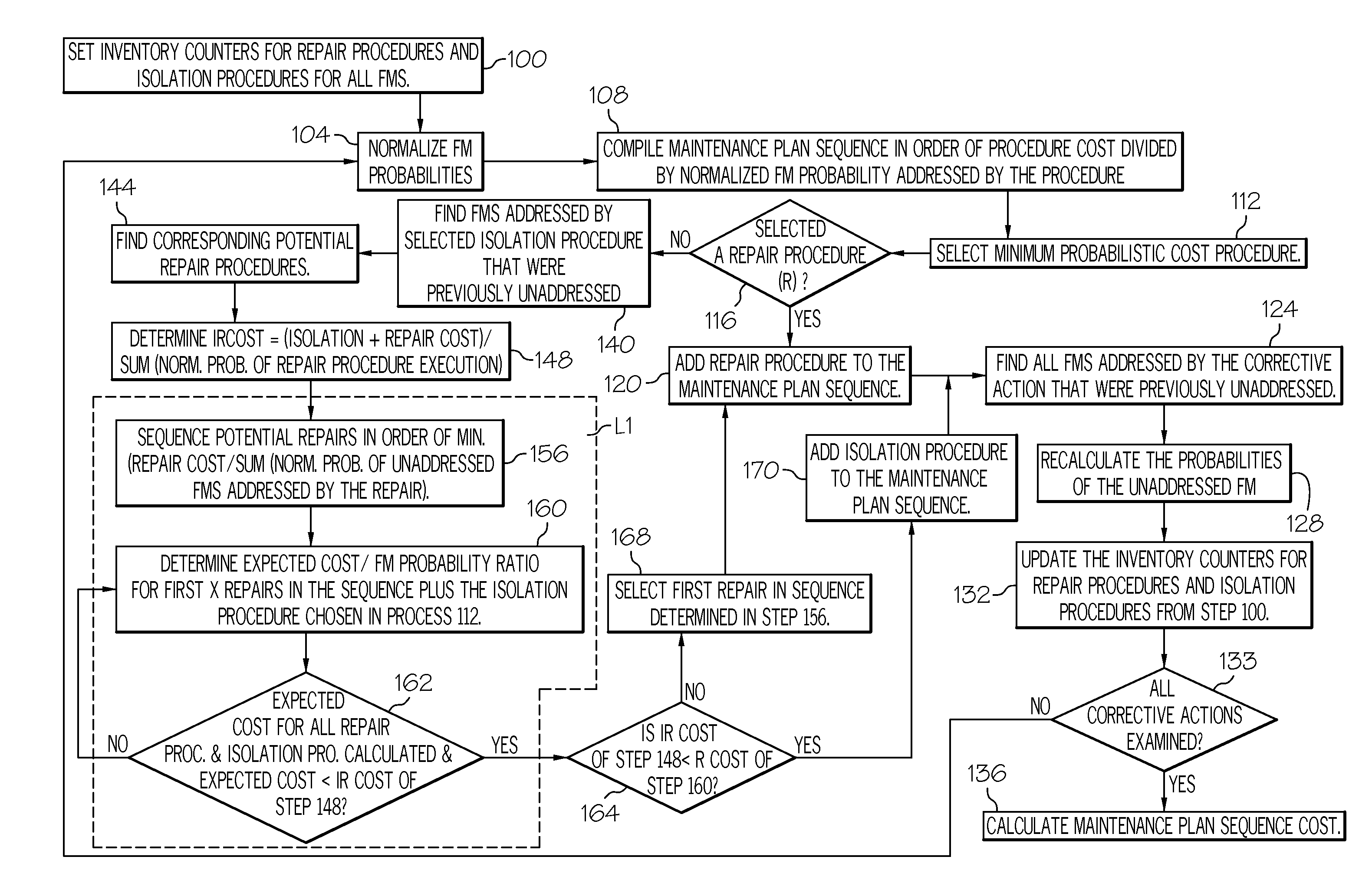
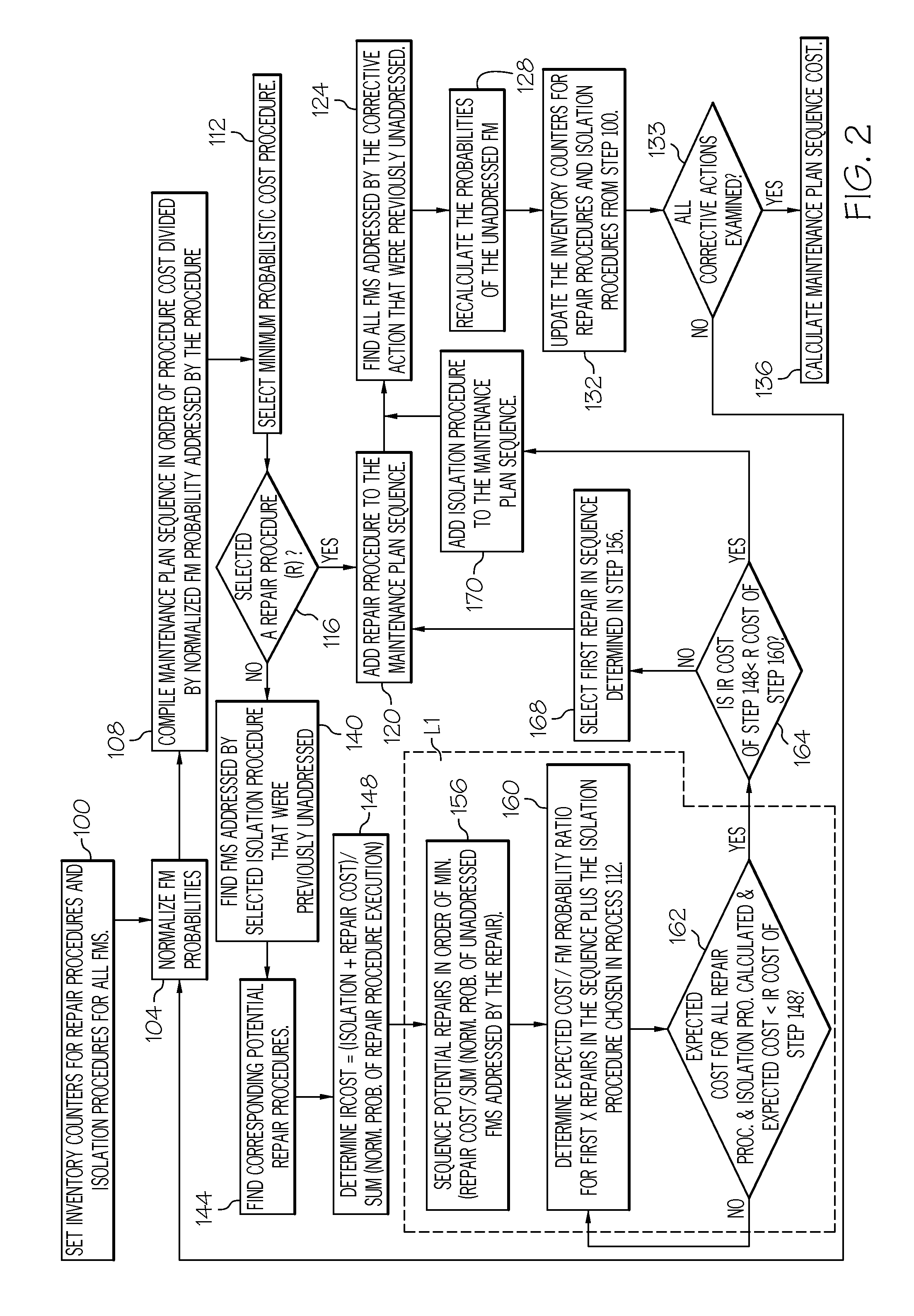
[0021]An alternative method, for producing a near optimal maintenance plan is presented ...


PUM


Abstract

Methods and apparatus are provided for determining a lowest total cost maintenance plan. The method comprises receiving a sequence of maintenance actions in an order of a waiting time for each maintenance action, wherein one of the maintenance actions is likely to repair the failure mode. Each maintenance action has an associated cost equal to a waiting time cost, an execution time cost and a material cost, wherein the waiting time of each maintenance action is the time required to requisition and receive material required to perform the maintenance action. The method also constructs a maintenance plan comprising a primary requisition and a secondary requisition by assigning each of the sequence of maintenance actions to one of the primary and secondary requisition.

Description

STATEMENT REGARDING FEDERALLY SPONSORED RESEARCH OR DEVELOPMENT[0001]This invention was developed with Government support under Contract W56HZV-05-C-0724 awarded by the United States Army. The Government has certain rights in this invention.TECHNICAL FIELD[0002]The present invention generally relates to the logistics and repair of complex systems. Specifically, it relates to computerized systems in the field of maintenance plan optimization.BACKGROUND[0003]Man has yet to invent a useful machine or a vehicle that can function throughout its designed useful life without some kind of maintenance or repair being performed. In fact, the lack of reasonable routine maintenance or repair will shorten the useful life of any asset, particularly for complex systems such as aircraft and manufacturing systems.[0004]When a useful asset suffers a casualty in the field, there are a number isolation tests that may be applied to disambiguate and to isolate the failure mode (“FM”), and then to narrow ...

Claims


Application Information

Patent Timeline
Patent Type & Authority Applications(United States)
IPC IPC(8): G06F11/07
CPCG06Q10/20
Inventor KOLBET, DAVID MICHAELPATANKAR, RAVINDRAMAGNUSON, RANDY R.
Owner HONEYWELL INT INC
Why Eureka
Try Eureka