Insole including an acupressure member
a technology of acupressure member and insole, which is applied in the field of insoles, can solve the problem that the connectionor can move its position within a limited range, and achieve the effect of convenient handling
- Summary
- Abstract
- Description
- Claims
- Application Information
AI Technical Summary
Benefits of technology
Problems solved by technology
Method used
Image
Examples
first embodiment
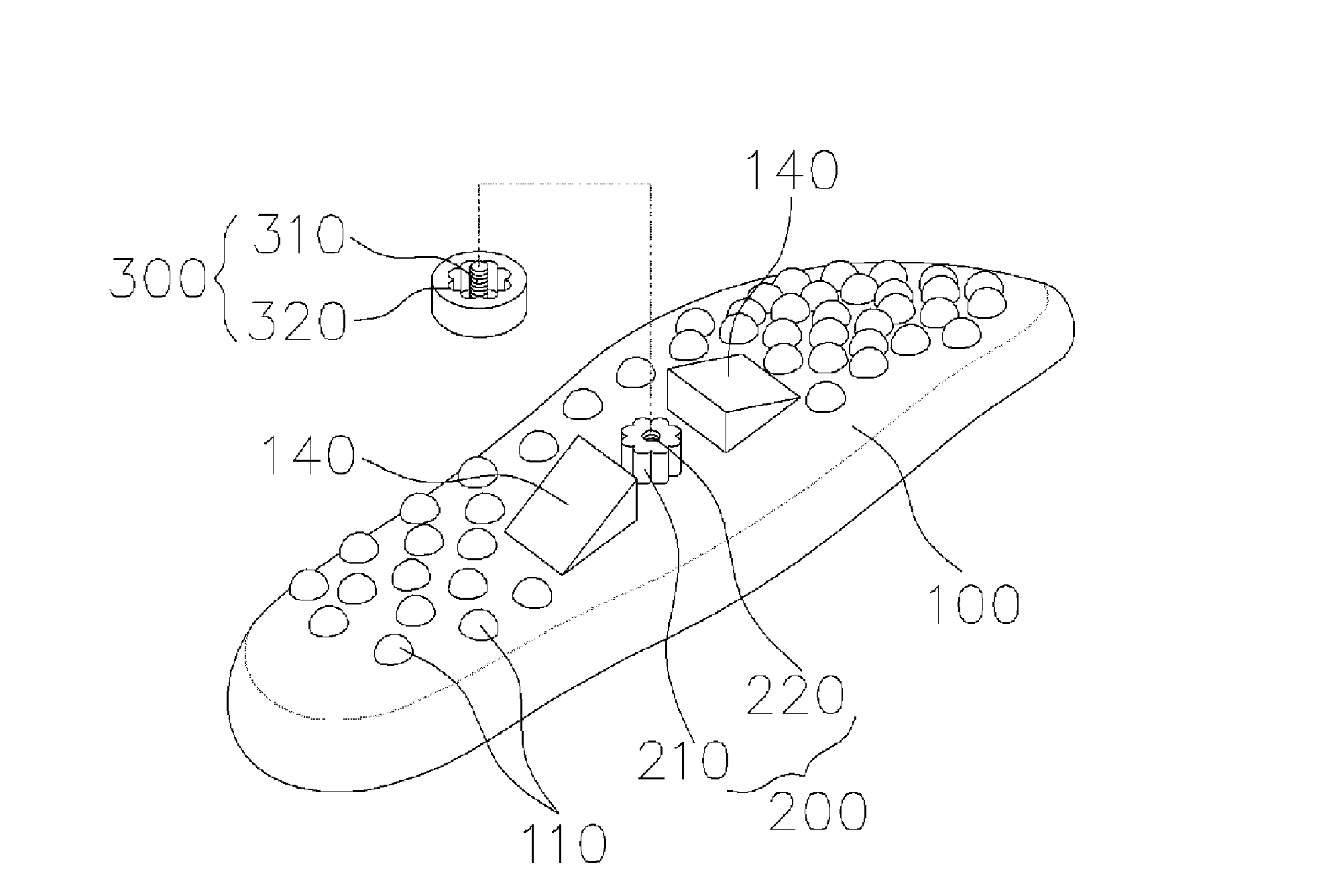
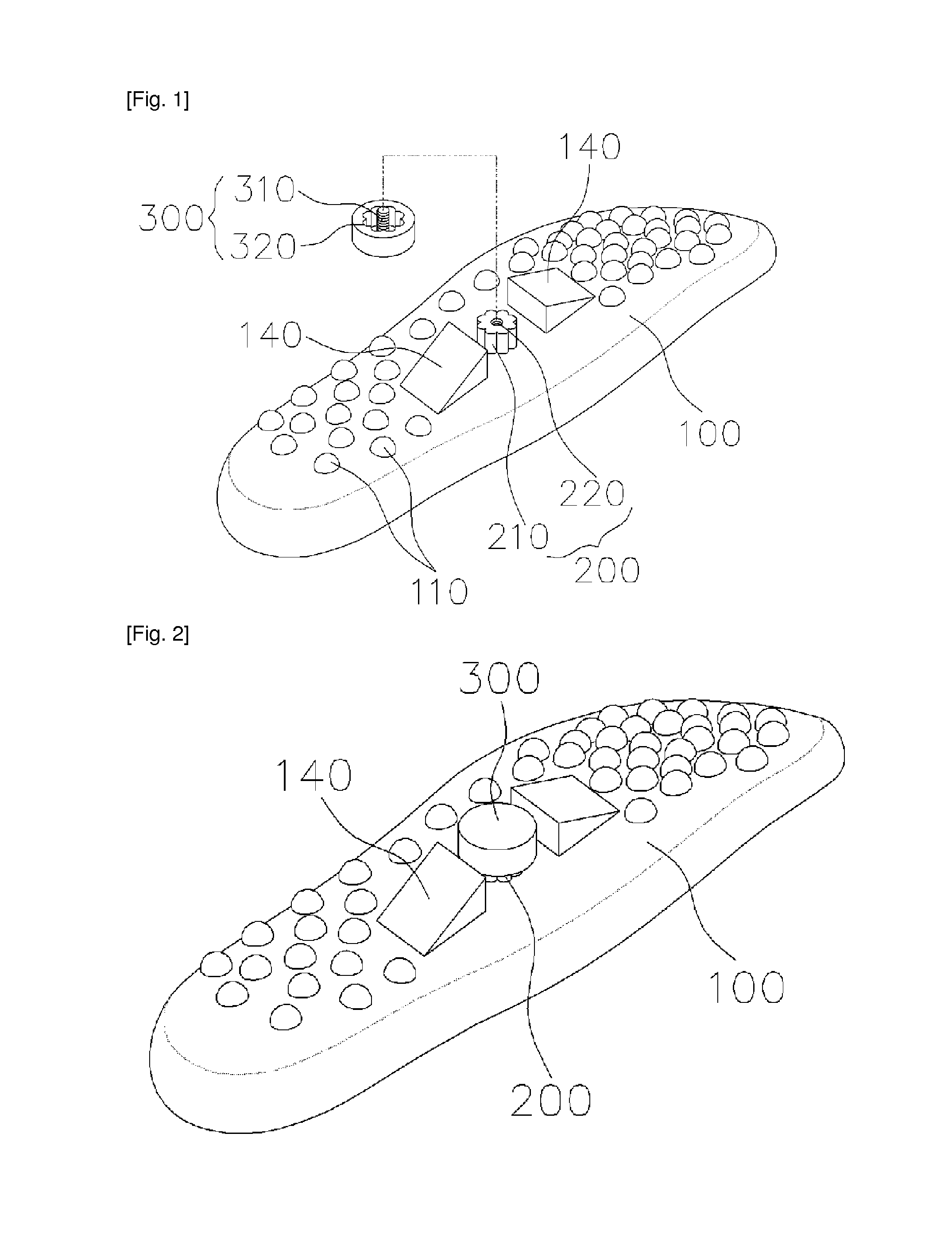
[0037]FIG. 1 is a schematic disassembled perspective view of a first embodiment of the present invention. FIG. 2 is a perspective view illustrating the engagement of FIG. 1.
[0038]The first embodiment of the present invention is featured in that the technology of the present invention is substantially adapted to the outsole in the shoes insole. Here, the shoes insole and the outsole, the midsole, the insole and Texon are given the same reference numeral.
[0039]As shown therein, from a region corresponding to the arched portion of the outsole 100 protrudes a connector 200, and the outer surface of the connector 200 is formed of continuously formed protrusions 210, and at the center is formed a female screw 220.
[0040]In the first embodiment of the present invention, the connector 200 is integrally fixed at the outsole 100. In the other embodiments of the present invention which will be described later, the connector 200 may be configured to be movable within a certain range.
[0041]The pr...
second embodiment
[0049]The insole including an acupressure member according to the present invention makes it possible to adjust basically the height of the acupressure member 300 and further makes it possible for the position of the acupressure member 300 to be movable. Here, the position of the acupressure member 300 is movable within a limited range which means the region of the arched portion.
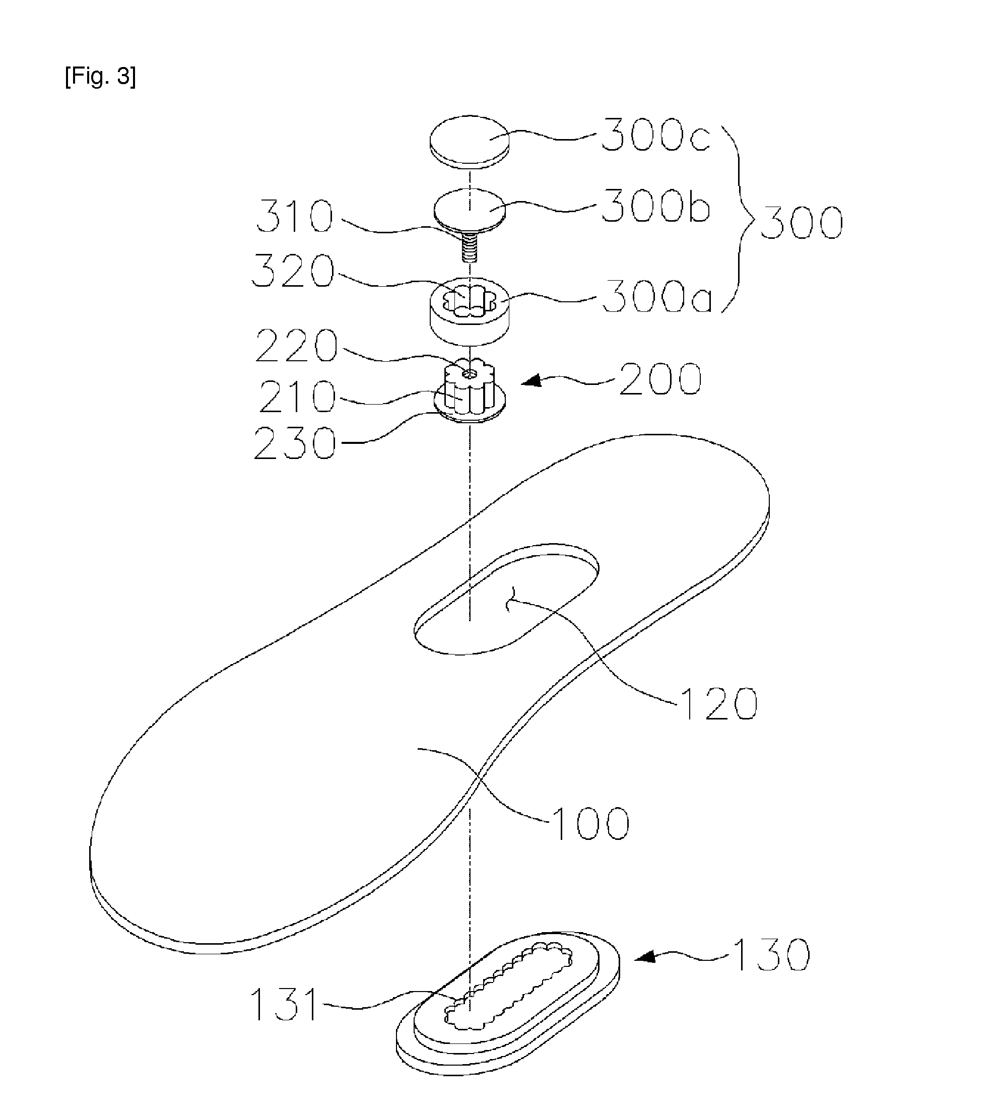
[0050]The second embodiment of the present invention is directed to the insole 100 featuring in that the acupressure member is formed at one portion among the outsole, the midsole, the insole or Texon. FIG. 3 is a disassembled perspective view illustrating an insole according to a second embodiment of the present invention. FIG. 4 is a perspective view illustrating the engagement of FIG. 3. FIG. 5 is a view of an operation state at a cross section taken along line A-A of FIG. 4. FIG. 6 is a view of an operation state at a cross section taken along line B-B of FIG. 4.
[0051]As shown therein, at the arched por...
third embodiment
[0058]FIG. 7 is a schematic disassembled perspective view of a third embodiment of the present invention. FIG. 8 is a perspective view illustrating the engagement of FIG. 7.
[0059]In the third embodiment of the present invention, the acupressure member 300 is formed at the upper surface of the insole 100, and the acupressure member 300 is formed of a curved surface in the same shape as a foot arch and an arched portion for thereby supporting the foot arch which is the center of the foot and the arched portion.
PUM
 Abstract
Description
Claims
Application Information
 - R&D
- Intellectual Property
- Life Sciences
- Materials
- Tech Scout
- Unparalleled Data Quality
- Higher Quality Content
- 60% Fewer Hallucinations
Browse by: Latest US Patents, China's latest patents, Technical Efficacy Thesaurus, Application Domain, Technology Topic, Popular Technical Reports.
© 2025 PatSnap. All rights reserved.Legal|Privacy policy|Modern Slavery Act Transparency Statement|Sitemap|About US| Contact US: help@patsnap.com


