Barrier-free floor threshold, in particular old building or renovation threshold

a barrier-free, floor-level technology, applied in the direction of condensed water draining off, doors/windows, building components, etc., can solve the problems of inability to meet the modern requirements for heat insulation, and inability to meet the modern requirements for floor-level thresholds. to prevent the connection profile from tilting, the effect of sealing the area safely and reliably

Inactive Publication Date: 2013-08-08
RAGER FREY CLAUDIA
View PDF1 Cites 18 Cited by
  • Summary
  • Abstract
  • Description
  • Claims
  • Application Information

AI Technical Summary

Benefits of technology

[0033]A development of the before-described embodiment is characterized in that an end element can be arranged at the connecting profile in a fastening groove provided there, in order to determine swiveling the additional limb or the intermediate part arranged there. As it is, this end piece forms the top limit of the roller pan, when it is then inserted in the groove. Swiveling is then easily possible. If the desired angle has been set, by means of the connecting piece then the intermediate part can be determined.
[0034]Furthermore, it is an advantage, if at the side of the connecting profile pointing at the floor a height adapting device is provided, that can be determined in a connecting groove formed at the connecting profile. This serves for preventing the connecting profile from tilting, when the height difference is such that the connecting piece cannot be supported with certain material. In order to avoid here a subsequent sinking or sliding or forming of fractures, the height adapting device is very advantageous, as it can be set to a once chosen height, and can then be determined. For this, for example, in the bottom area there is a plate-like support element that is supported on the floor, that engages by means of an adjusting screw at the top part of the height adjusting device. If the thread is set to the desired level, by means of one or two counter nuts the height adjusting device can be determined. As already mentioned, the configuration with an intermediate part at the connecting profile is configured such, that, for example, at the intermediate part carrying the roller, at the side facing outwards, a slid-in groove is formed in order to receive the additional limb. Now it is possible to add the additional limb of any length. For example, if the material of the limb for the height compensation function is too long, it is possible without any problems to cut off a piece of the additional limb. This is usually performed with standard working means, and does not have the disadvantage of a weakening of the material.
[0035]The invention is also characterized in that a sealing can be arranged, in particular by means of a coated metal at the underside of the basic body. This sealing serves for sealing the exterior area, for example outside a building, such as a balcony, an outdoor terrace or the like, against the interior area. During construction often the area is neglected where the floor thresholds are arranged. The sealing is provided for sealing this area safely and reliably. This avoids that later defective constructions have to be removed because exactly this sealing has been forgotten. The sealing can be fastened here advantageously by welding, cold or heat adhesion at the basic body. It is advantageously fastened here such that it is arranged at the floor threshold before this is finally fixed or attached to the floor. The sealing sheeting of the sealing is here designed in such a way that it can be guided, for example, so far that it reaches beyond the additional limb of the connecting profile. However, at least it should be guided so far, that it reaches, for example, still beyond the area of the height adjustment device, in order to seal this area safely. Further outwards then, of course, as usual, another sealing sheeting can be connected to or glued over it.

Problems solved by technology

However, there is the problem with the so-called renovation or old building thresholds, that because no changes of the floor construction should or could be carried out, there is no floor extension of such a floor threshold.
The problem with such barrier-free floor thresholds is now, on the one hand, to create a passage that allows to be over-rolled by wheelchairs, sick beds, walkers or the like, however, at the same time to guarantee a safe sealed protection, and, most of all, also heat protection in the area between the floor and the door or its bottom edge.
An often occurring problem is here, that the thermal separation, in particular of metal thresholds, is extremely complicated.
Thus the state of the art does not succeed, because of the flat construction of such a threshold, in realizing a thermal separation according to today's requirements of building owners and architects.
Furthermore, the discussed thresholds are often of light metal or metal, what, of course, implicates that these materials have a good heat conductivity, what is just not desired.
Another problem is the fact, that in the direction of assembling the floor threshold, if it is of light metal or metal, also a heat conduction occurs, as it were, from the top to the bottom into the floor, so that here also a thermal separation has to be performed.
The floor thresholds known in the state of the art do not comply with the modern requirements with regard to heat insulation and in particular heat conductivity behavior.
In particular, if magnetic seals form at least a part of the sealing arrangement of the door or the window, there is another problem in the state of the art, namely, that possibly moisture intruding in the grooves in the floor threshold or its basic body, or the possibly intruding water, has to be drained.
Because of the very flat design or construction of the barrier-free floor threshold, it was not possible so far in the state of the art to develop a suitable drainage concept that guarantees an even flatter construction than the one used so far.

Method used


Image

  • Barrier-free floor threshold, in particular old building or renovation threshold
  • Barrier-free floor threshold, in particular old building or renovation threshold
  • Barrier-free floor threshold, in particular old building or renovation threshold

Examples


Embodiment Construction

[0051]In the figures identical or corresponding elements each are indicated by the same reference numbers, and therefore are, if not useful, not described anew.

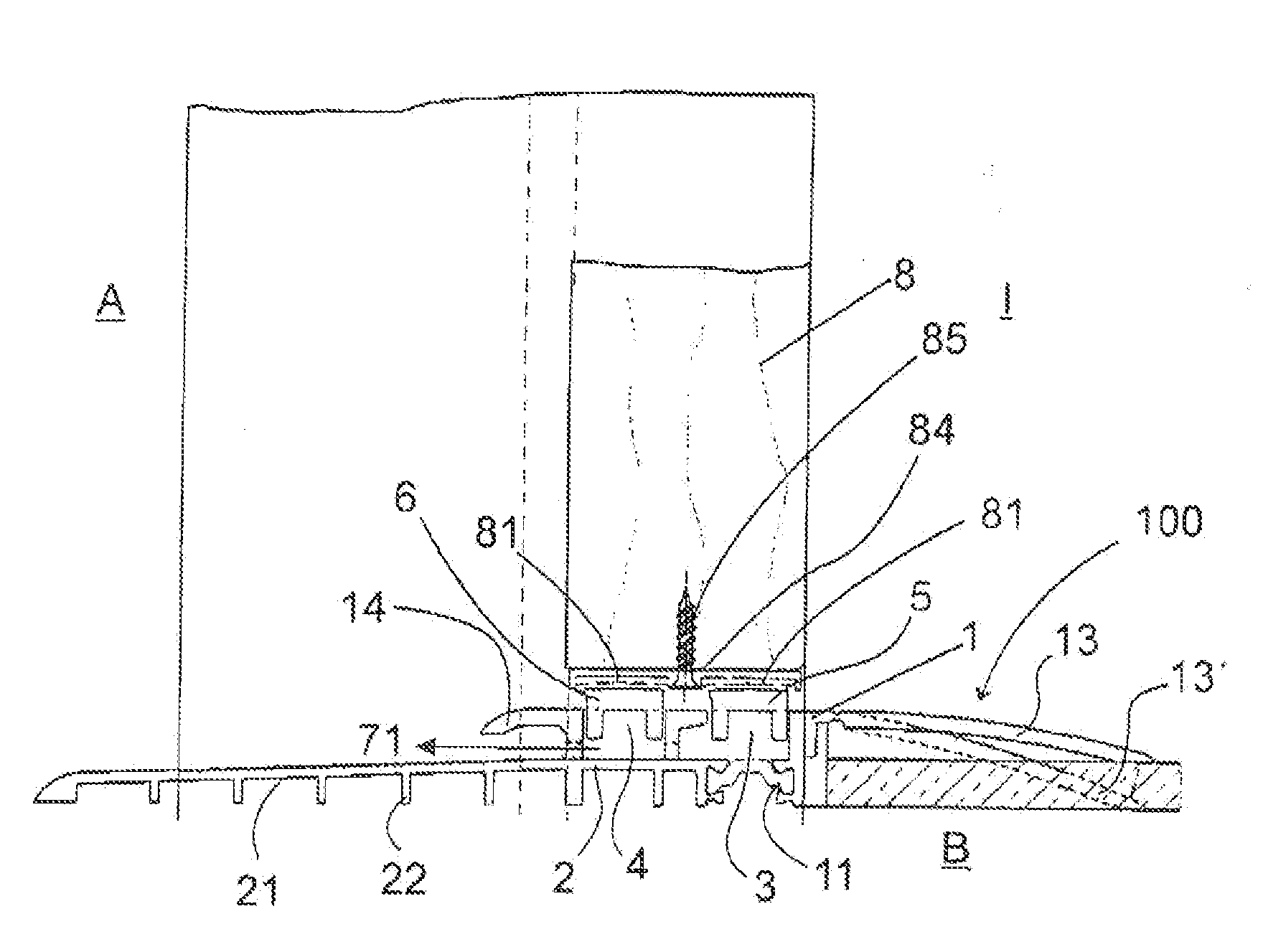
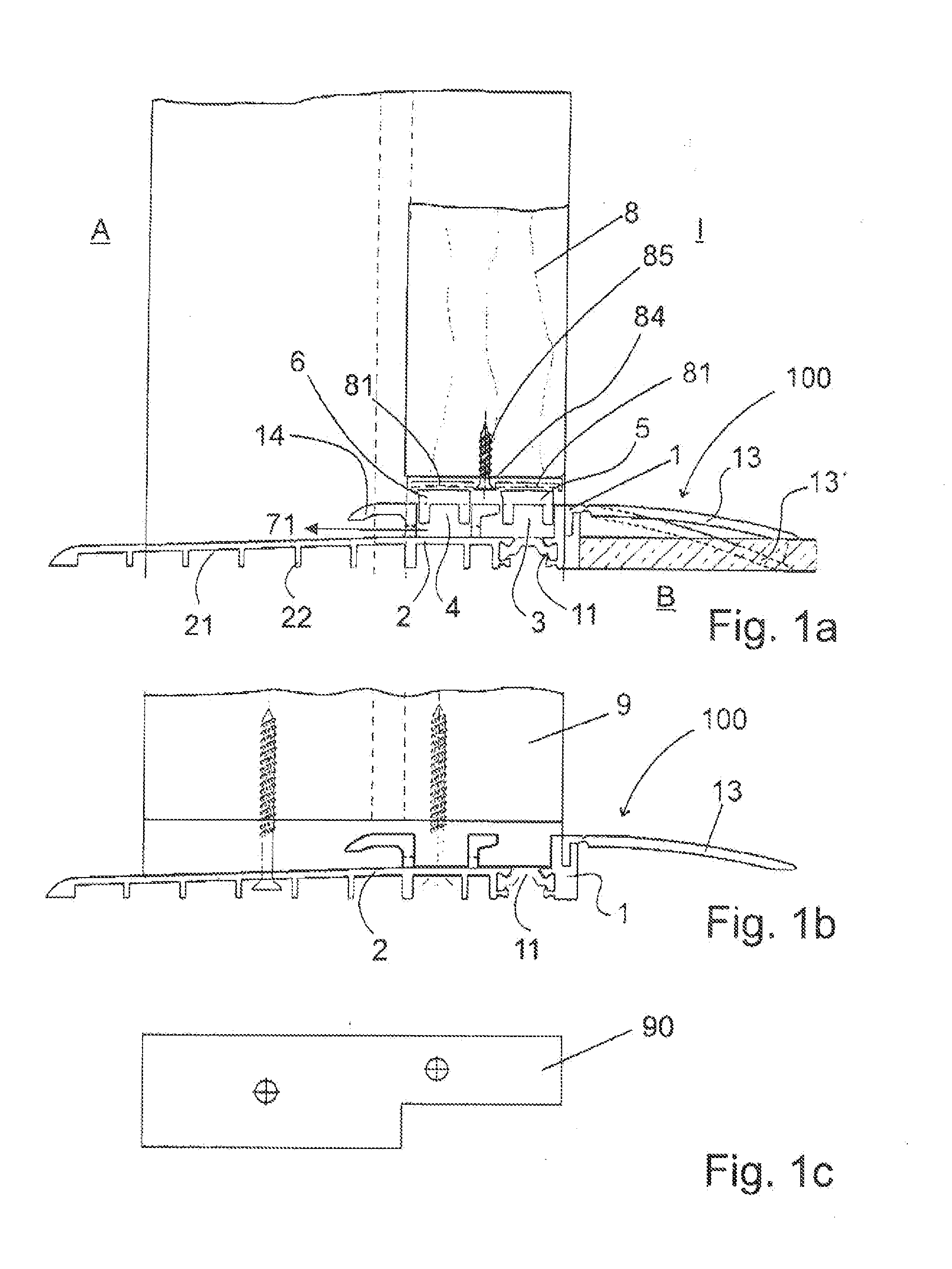
[0052]FIGS. 1a to 1c show a first embodiment of a floor threshold 100 according to the invention. The basic body 1 is here located, at least partly, on the side facing inwards I. In FIG. 1a an inner limb 13 is provided that can be bent in towards the floor B. This is shown with a dashed line and indicated by the reference number 13c. In the basic body 1, the grooves 3 and 4 are located for receiving the magnetic seal strips 5 and 6. The magnetic seal strips 5 and 6 are attracted by the counter magnet 81 when they are congruent, that is, when the door is closed. The door wing is indicated here by reference number 8, while in FIG. 1b a frame is shown that has reference number 9. A first thermal separation 11 separates thermally the basic body 1 from the inner area towards the outer area. Furthermore, the basic body 1 is formed ...


PUM


Abstract

The invention refers to a barrier-free floor threshold, in particular old building or renovation threshold that can be put on a finished floor, wherein the floor threshold seals an exterior area of a building against an interior area, or two rooms against each other, while interacting with a window or a door, comprising a basic body, having at least one, preferably two grooves for receiving magnetic seal strips, wherein a first thermal separation is provided on the side of the basic body pointing inwards, and wherein a bottom end element is arranged on the side of the basic body facing the floor in order to limit a flume that connects the grooves with an outlet provided on the outside of the basic body.

Description

[0001]The invention refers to a barrier-free floor threshold, in particular old building or renovation threshold that can be put on a finished floor, wherein the floor threshold seals an exterior area of a building against an interior area, or two rooms against each other, while interacting with a window or a door.BACKGROUND OF THE INVENTION[0002]Floor thresholds of this type are known. However, there is the problem with the so-called renovation or old building thresholds, that because no changes of the floor construction should or could be carried out, there is no floor extension of such a floor threshold. In particular, when, as in the present invention, the rooms should be separated barrier-free, or an interior room should be separated from an exterior area, it is necessary to design these thresholds very flat, as the regulations for nursery homes, hospitals or altogether for barrier-free rooms do not allow anymore an elevation even up to 2 cm. Accordingly, modern thresholds have...

Claims


Application Information

Patent Timeline
Patent Type & Authority Applications(United States)
IPC IPC(8): E06B1/70
CPCE06B1/70E06B7/14E06B1/702E06B2001/707
Inventor RAGER-FREY, CLAUDIA
Owner RAGER FREY CLAUDIA
Why Eureka
Try Eureka